Motor, Thrust bearing, Hopper, and Flange assembly for a DIY Filament Extruder
thingiverse
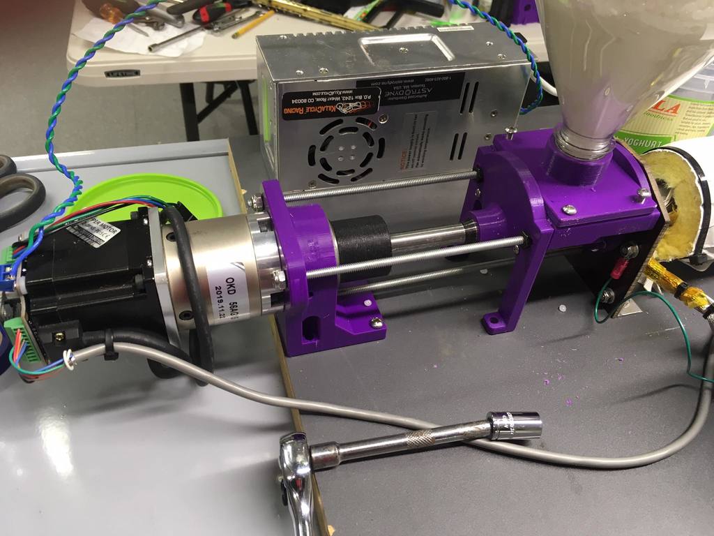
This motor, thrust bearing, hopper, and flange assembly for a DIY filament extruder simply and effectively deals with the auger thrust forces that tend to cause difficulty with many home extruders. This is a redesign/remix of the front end of the RepRapable RecycleBot by Joshua Pearce: https://www.thingiverse.com/thing:2937584. Please visit this link as it contains the rest of this marvelous machine. The extruder auger develops a large amount of thrust as it forces a stream of plastic out of the nozzle on the end of the barrel. This thrust tends to push the barrel forward and the auger backward. These components need to be connected together directly, so that they don't bend away from each other, and cause the auger and the barrel to go out of alignment. (This makes even _more_ thrust as the auger rubs against the wall of the barrel, bending them further out of alignment. This process eventually runs away and stalls the motor.) There are three #10-24 (~5mm) threaded rods placed symmetrically around the auger and the barrel. They run from the motor bearing mount _through_ the pellet hopper and the heat break, and connect to the barrel flange.These carry the very large thrust force between the barrel and the auger. Thus, the parts won't tend to defect and bend with the thrust forces. Fashion the heat break plate from a strong heat resistant material like FR4 or G-10 or perhaps even carbon fiber. After all the thrust line components are assembled to each other, trim the heat break to the mounting bed surface and fashion a short section of aluminum angle to attach it to the mounting bed. It has to be strong, since it still reacts the turning (torque) of the auger to the mounting bed. I designed all these parts so that the center line (thrust line) of this assembly is 50 mm above the mounting bed surface, just to be consistent. All of the hopper and barrel parts should be assembled on a ~9/16" (16mm) shaft (or whatever size you have decided on for your auger.) The heat break and the flange should be match drilled to the bolt circle holes in the hopper and then these screws should be installed. Then you match drill the barrel flange to the threaded rod holes in the hopper. This will keep all of the parts perfectly aligned with the auger. The motor/bearing mount holds a commonly used tapered roller bearing from a trailer wheel. The bearing is lightly greased before it is put in place. This 1" ID bearing can be bought in any auto parts store. The part number is: L44643 Here is a link to the part in McMaster-Carr: https://www.mcmaster.com/5709K82/ The GearMotorCoupler should be printed out of strong material such as nylon or perhaps PET-G. The two auger set screws are important to insert and to tighten as they prevent the auger from pushing on the end of the gear box shaft. (The front gear box bearing will quickly fail if it is subjected to the thrust of the auger.) Make sure that the coupler is seated against the bearing before you tighten the set screw on the gear box shaft. You may wish to run the auger slowly a bit (with plastic in the hopper) before you tighten the gear box shaft set screw. Be sure to put all four mounting screws in the base to hold the AugerMotorBracket to the mounting bed. It still reacts all the auger torque, even though the threaded rods are reacting the thrust. The AugerMotorBracket should be printed on its back (motor face) and should be printed out of PET-G, but PLA would likely work fine. The HopperLegs can be printed out of PLA, as can the HopperScrewCap. The HopperTrough should be printed out of some strong, heat resistant material, such as PET-G, ABS, or Nylon. The HopperInsulationFlat is included simply to use as a template for cutting out and drilling the actual heat break out of FR4, G-10, fiberglass, or some other strong, heat resistant, insulative material.
With this file you will be able to print Motor, Thrust bearing, Hopper, and Flange assembly for a DIY Filament Extruder with your 3D printer. Click on the button and save the file on your computer to work, edit or customize your design. You can also find more 3D designs for printers on Motor, Thrust bearing, Hopper, and Flange assembly for a DIY Filament Extruder.