Motorized Cube Gears
thingiverse
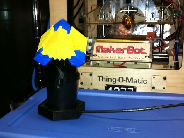
This DIY project involved motorizing Emmett's Cube Gears by first selecting an appropriate motor and then designing three parts to morph one of the big corner gears into a motor attachment. The assembly process entailed removing specific corners, gluing nuts and drive shaft components together, attaching the motor to the gear flange, and reattaching the smaller corners. A USB extension cable was also added for power, and the motor was epoxied into place. Although the current motor provides barely enough power, fine-tuning friction could improve performance. View the project's video at http://www.youtube.com/watch?v=TjBAd8S2Yms and find the updated drive shaft design at http://www.hmimotors.com/New_Pages/3440.htm.
With this file you will be able to print Motorized Cube Gears with your 3D printer. Click on the button and save the file on your computer to work, edit or customize your design. You can also find more 3D designs for printers on Motorized Cube Gears.