Motorized Telescope Filter Wheel (adapter)
thingiverse
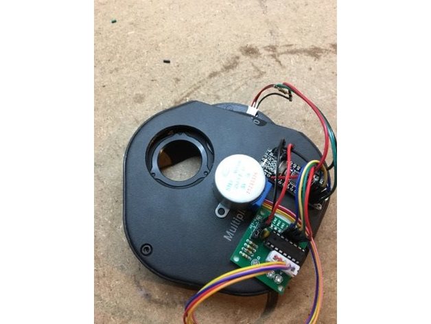
Pictures do not show the cover This adapter and code was created to be able to motorize a cheap, common, filter wheel. Normally this requires a lot of plates, adapters and big stepper motors which add more and more weight. They also have bigger power requirements. By printing a small adapter and replacing a threaded insert you can get a low weight, direct driven, filter wheel with good positional accuracy and homing features for a considerable cheaper cost (my total is £40) than just buying something off the shelf. The source code for the Arduino and ASCOM-driver, as well as a setup for the driver, is located here: https://github.com/Pipshag/MilkyWheel Below follows quick instructions: This repository contains both the Arduino as well as ASCOM code (and compiled driver) to be able to motorize a Filter Wheel, often used in Astrophotography. Material: Filter Wheel (this design uses a no-name filter wheel labeled "Multiple 5-Filter Wheel") Arduino Nano (for low weight) 28BYJ-48 5V stepper motor (able to run off the USB-connection) ULN2003 shield (often included with the stepper) Hall sensor US5881LUA (for autocalibration) 3D Printed Direct Drive adapter 3D Printed Wheel Cover Build: Wire accordingly -- Connect 28BYJ-48 with stepper cable to ULN2003 -- Pins digital 8, 9, 10, 11 to ULN2003 pins IN1, IN2, IN3, IN4 -- Pin digital 12 to Hall Sensor (data) -- Pin 5V and Ground to ULN2003 5V+ and Ground -- Pin 3.3V and Ground to Hall Sensor (Positive and Ground) -- Connect 10K resistor on Hall Sensor between Positive and Data Remove the two center screws and two hex screws on the back side. Remove back plate. In the center of the filter disc you'll see a threaded insert, remove this. Take the 3D printed adapter and make sure it fits. Also make sure your stepper motor axle fits inside the adapter hole. Then, remove the adapter and use some CA-glue on the outside of the adapter before inserting it fully. I used some Accelerator to make it bond really well. Don't use glue for the stepper shaft since you might probably want to remove the front disc one day. Assemble everything again and then mount the stepper by pushing it inside the adapter. I glued the Hall Sensor on the opening of the case and used a small neodymium magnet which I glued to the center disk after getting a good position with my Arduino. Open the Arduino ino file and check the settings. Calibration offset is a good way to make sure you can get a great 0 position even if things change mechanically over time. Hall Sensor Wiring with Pullup resistor: "To use connect power to pin 1 (all the way to the left), ground to pin 2 (middle) and then a 10K pull up resistor from pin 3 to power. Then listen on pin 3, when the south pole of a magnet is near the front of the sensor, pin 3 will go down to 0V. Otherwise it will stay at whatever the pullup resistor is connected to. Nothing occurs if a magnet's north pole is nearby (unipolar)." Pin 1 is the pin to the left when the Hall Sensor is resting with the flat side on a table.
With this file you will be able to print Motorized Telescope Filter Wheel (adapter) with your 3D printer. Click on the button and save the file on your computer to work, edit or customize your design. You can also find more 3D designs for printers on Motorized Telescope Filter Wheel (adapter).