Motorized Turntable for 3D Scanning
thingiverse
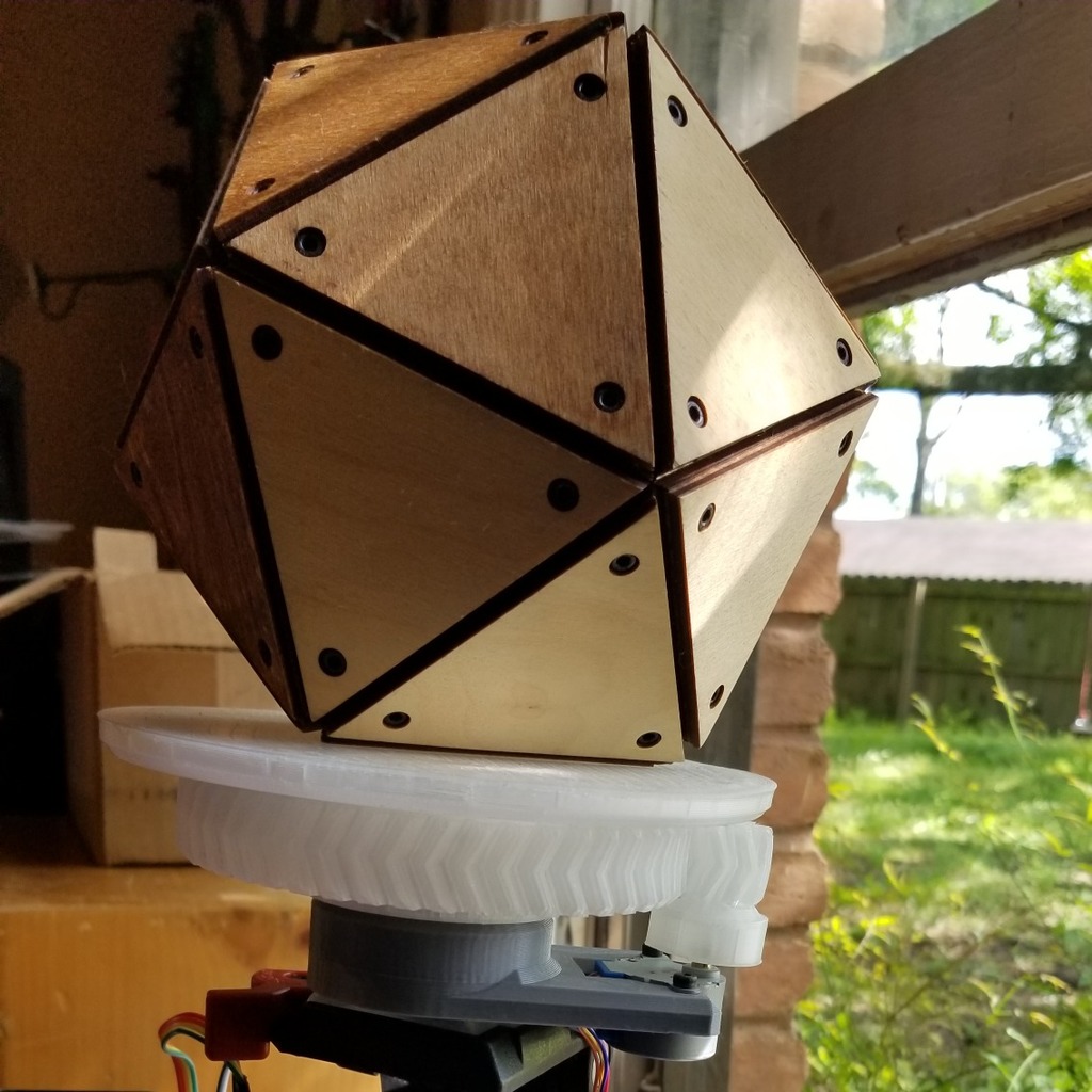
This unit is made to fit a 2BYJ-48 stepper, some 3D printed gears, and then self-tap onto a threaded tripod! Some assembly is required, as you will have to supply your own electronics and base. And as a quick note, the base file is called the 'KinectScanMainMount' because I designed it to rotate the piece I was scanning while my Kinect captured the depth data. UPDATE #1: Added the gears and tray needed for assembly. Will be testing soon. UPDATE #2: A few minor tweaks made so everything would fit nicely. Second round of tests commencing shortly. UPDATE #3: Alright, things seem to be looking fit and ready so I'm going to remove the work-in-progress designation and hope for the best! [Here it is in action](https://www.youtube.com/watch?v=l_sDvCMXHp8) + [Video Tutorial for anyone interested in learning the basics of Kinect scanning](https://youtu.be/yXZRvrnQ51w) Needs: 1x KinectScanMainMount.stl 1x TurntableGearLarge.stl 1x TurntableGearSmall.stl 1x TurntableTray.stl (You choose whether you'd like it with or without quadrants - example in picture set above) 2x M3 screws to fix tray to large gear 1x [2BYJ-48 stepper motor and driver](https://smile.amazon.com/ELEGOO-28BYJ-48-ULN2003-Stepper-Arduino/dp/B01CP18J4A) 1x [Arduino microcontroller](https://smile.amazon.com/LAFVIN-ATmega328P-ATMEGA16U2-Compatible-Arduino/dp/B07GDKLLMJ/) 1x [9V 1A power supply adapter](https://smile.amazon.com/Arduino-power-supply-adapter-110V/dp/B018OLREG4) 1x Standard threaded tripod or base of your choosing. Arduino setup for beginners: 1. Make sure you have the [Arduino IDE](https://www.arduino.cc/en/main/software) installed on your computer. 2. Following the general steps in [this tutorial](https://www.youtube.com/watch?v=lmMTsbSbHC8), use the Male-to-Female jumper wires to connect the Arduino pins 2,3,4, and 5 to IN1, IN2, IN3, and IN4 on the ULN2003 stepper driver. **(Not pins 8-11 shown in the video!)** 3. Connect the 5V and GND pins to the + and - pins on the stepper driver. 4. Copy and paste the following sketch into the IDE, then hit the 'Upload' arrow in the top left under the menu: <code> //Put all the pins in an array to make them easy to work with int pins[] { 2, //IN1 on the ULN2003 Board, BLUE end of the Blue/Yellow motor coil 3, //IN2 on the ULN2003 Board, PINK end of the Pink/Orange motor coil 4, //IN3 on the ULN2003 Board, YELLOW end of the Blue/Yellow motor coil 5 //IN4 on the ULN2003 Board, ORANGE end of the Pink/Orange motor coil }; //Define the wave drive sequence. //With the pin (coil) states as an array of arrays int waveStepCount = 4; int waveSteps[][4] = { {HIGH,LOW,LOW,LOW}, {LOW,HIGH,LOW,LOW}, {LOW,LOW,HIGH,LOW}, {LOW,LOW,LOW,HIGH} }; //Define the full step sequence. //With the pin (coil) states as an array of arrays int fullStepCount = 4; int fullSteps[][4] = { {HIGH,HIGH,LOW,LOW}, {LOW,HIGH,HIGH,LOW}, {LOW,LOW,HIGH,HIGH}, {HIGH,LOW,LOW,HIGH} }; //Define the half step sequence. //With the pin (coil) states as an array of arrays int halfStepCount = 8; int halfSteps[][4] = { {HIGH,LOW,LOW,LOW}, {HIGH,HIGH,LOW,LOW}, {LOW,HIGH,LOW,LOW}, {LOW,HIGH,HIGH,LOW}, {LOW,LOW,HIGH,LOW}, {LOW,LOW,HIGH,HIGH}, {LOW,LOW,LOW,HIGH}, {HIGH,LOW,LOW,HIGH} }; //Keeps track of the current step. //We'll use a zero based index. int currentStep = 0; //Keeps track of the current direction //Relative to the face of the motor. //Clockwise (true) or Counterclockwise(false) //We'll default to clockwise bool clockwise = true; // How many steps to go before reversing, set to zero to not bounce. //int targetSteps = 0; //targetSteps 0 means the motor will just run in a single direction. //int targetSteps = 2048; //2049 steps per rotation when wave or full stepping int targetSteps = 4096; //4096 steps per rotation when half stepping void setup() { // put your setup code here, to run once: Serial.begin(9600); for(int pin = 0; pin < 4; pin++) { pinMode(pins[pin], OUTPUT); digitalWrite(pins[pin], LOW); } } void step(int steps[][4], int stepCount) { //Then we can figure out what our current step within the sequence from the overall current step //and the number of steps in the sequence int currentStepInSequence = currentStep % stepCount; //Figure out which step to use. If clock wise, it is the same is the current step //if not clockwise, we fire them in the reverse order... int directionStep = clockwise ? currentStepInSequence : (stepCount-1) - currentStepInSequence; //Set the four pins to their proper state for the current step in the sequence, //and for the current direction for(int pin=0; pin < 4; pin++){ digitalWrite(pins[pin],steps[directionStep][pin]); } } void loop() { //Comment out the Serial prints to speed things up //Serial.print("Step: "); //Serial.println(currentStep); //Get a local reference to the number of steps in the sequence //And call the step method to advance the motor in the proper direction //Wave Drive //int stepCount = waveStepCount; //step(waveSteps,waveStepCount); //Full Step //int stepCount = fullStepCount; //step(fullSteps,fullStepCount); //Half Step int stepCount = halfStepCount; step(halfSteps,halfStepCount); // Increment the program field tracking the current step we are on ++currentStep; // If targetSteps has been specified, and we have reached // that number of steps, reset the currentStep, and reverse directions if(targetSteps != 0 && currentStep == targetSteps){ currentStep = 0; // clockwise = !clockwise; } else if(targetSteps == 0 && currentStep == stepCount) { // don't reverse direction, just reset the currentStep to 0 // resetting this will prevent currentStep from // eventually overflowing the int variable it is stored in. currentStep = 0; } //2000 microseconds, or 2 milliseconds seems to be //about the shortest delay that is usable. Anything //lower and the motor starts to freeze. //delayMicroseconds(2250); delay(1); } </code> + Once that's done, disconnect the Arduino from the computer, plug it into the power cable, and connect the stepper to the stepper driver. Your turntable should now function! [Like this](https://www.youtube.com/watch?v=ecsKvfNM28w) Note: you can hear my 3D printer in the background, the turntable itself is essentially silent. **Be aware that leaving this running for large amounts of time can cause a lot of heat on the Arduino, so be careful!**
With this file you will be able to print Motorized Turntable for 3D Scanning with your 3D printer. Click on the button and save the file on your computer to work, edit or customize your design. You can also find more 3D designs for printers on Motorized Turntable for 3D Scanning.