Mounting Plate Frame for 8x8 LED Module Array Matrix
thingiverse
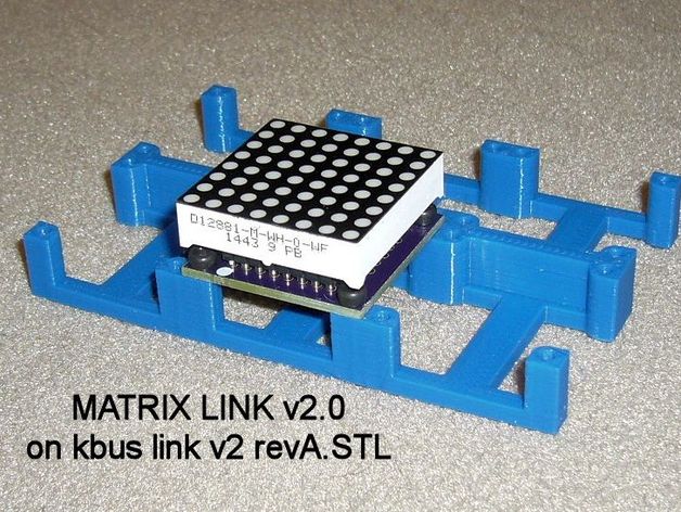
This design allows for the installation of multiple 8x8 LED array modules. The design is highly configurable, enabling users to customize the number of LED arrays in both horizontal and vertical directions, making it adaptable to a wide range of applications. The frame itself remains compact, matching the dimensions of the mounted LED arrays; this minimalist approach enables the use of zip ties or other mechanical fasteners to connect multiple frames for larger displays that can't be printed at once. The driver chips on the circuit boards for the LED arrays typically utilize Maxim MAX7219 or MAX7221, or AMS AS1106 or AS1107. Boards featuring SOIC packaged driver chips can be designed to match the 8x8 LED matrices perfectly. In contrast, boards with DIP packaged driver chips are larger and have the DIP driver chip located outside the LED matrix. The original design was developed specifically for use with "LED Matrix Link v2.0," available at https://oshpark.com/shared_projects/J1PUJCGP. The v2.0 board is an adaptation of the LED Matrix Link board available from https://friedcircuits.us/. I preferred the friedcircuits approach since it positions the SOIC driver chip on the side of the board away from the LED module, enhancing its ability to dissipate any generated heat. This approach also allows for the use of right-angle headers to interconnect LED modules. My v2.0 revision was driven by a preference for through-hole capacitors and resistors and a desire to increase trace widths, especially for the 5V power daisy chain used in multiple modules. I also trimmed the board dimensions slightly, adjusted the placements of the four mounting holes to provide more room for screw heads, and added silkscreen for a serial number label. The rev A version of the openSCAD script adds flexibility when handling different types of module boards. In addition to the original v2.0 Matrix Link, sample dimension data is provided in the openSCAD file for the Friedcircuits Matrix Link v1.2, generic boards marked as FC-16 type, and larger generic boards using DIP-style MAX7219 driver chips located outside the LED array. Selection of the desired board type is handled through commenting or uncommenting the appropriate dimension data. Sample STL files are provided for 3-by-2 configurations of the frame for the Matrix Link v2.0, Friedcircuits Matrix Link v1.2, and FC-16 type driver boards. The sample STL file for the DIP-style MAX7219 is provided in a 3-by-1 configuration, all with mounting holes sized for threading M2.5 hardware. The openSCAD file has been extensively commented to aid those who wish to tailor the design further. Printer Settings: - Printer Brand: RepRap - Printer: MakerFarm i3v - Rafts: No - Supports: No - Resolution: 0.2mm - Infill: 20% or as desired Post-Printing Notes: If there are burrs on the edges of the circuit boards used, file or sand them away so adjacent boards can fit tightly together. Mounting hardware must be used to attach the boards to the printed frame; this means the LED arrays cannot be directly soldered to the boards. Single Inline Package (SIP) sockets should be soldered to the boards, and the LED arrays inserted into the SIP sockets.
With this file you will be able to print Mounting Plate Frame for 8x8 LED Module Array Matrix with your 3D printer. Click on the button and save the file on your computer to work, edit or customize your design. You can also find more 3D designs for printers on Mounting Plate Frame for 8x8 LED Module Array Matrix.