Mousetrap Car
thingiverse
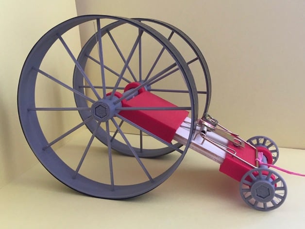
This project uses a standard household mousetrap to create a spring powered car. It can be used at a variety of age levels, for fun and experimentation with different wheel sizes; to applying measurement skills and basic geometry to find ratios and distances; to exploring energy conservation, work, and spring constants. It can be used for a #MathProject, #ScienceProject, or #EngineeringProject. Print Settings Printer Brand: MakerBot Printer: MakerBot Replicator (5th Generation) Rafts: Yes Supports: No Resolution: Fine Infill: 50% Notes: When printed pretty solidly, (with Standard Makerbot settings but 4 shells and 50% infill), the drive axles (DriveAxleMale.STL and DriveAxleFemale.STL) and the 125mm drive wheels (DriveWheel125.STL) will take almost 8 hours to print, but will all fit together on the platform of the MakerBot Replicator. The front axles (FemaleAxle.STL and MaleAxle.STL) will take about 90 minutes together and the front wheels will depend on the diameter you choose, but average about half an hour per pair. The front end takes about 1 hour and 45 minutes and is shorter than the rear end, to accommodate the non-symmetry of the mousetraps. The rear end takes about 2 1/2 hours and has a notch in it to allow for the spooled string when it is wound on the axle. How I Designed This These pieces were designed on #OnShape to be printed on a #MakerBot Replicator. You can also print the parts on a MakerBot Mini, but you’ll be limited to the 85mm diameter drive wheel. If you wish to use these models as a foundation for further designs, I’ve created a public copy with OnShape named Mousetrap Car. Overview and Background Mousetrap cars convert spring energy into kinetic energy through linear and circular motion. By experimenting with mousetrap cars, your students can learn about gear ratios, circumference and radius, lever arms, friction, conservation of energy, velocity, work, and spring constants. Lesson Plan and Activity Overview Depending on your age group, you can provide prebuilt mousetrap cars with different sized wheels and allow them to choose the car they wish to experiment with, or you can allow them to specify the sizes and types of wheels they wish for their cars and then return to assembling and collecting data from the cars once all the printing has been accomplished. Assembly of the Mousetrap Cars To assemble the mousetrap cars, you will need the front and rear ends, the front and drive axles, a set of drive wheels, a set of front wheels, white glue, a standard mousetrap (about 3 7/8" by 1 7/8"), a pair of pliers, about 6 inches of string, and about a yard of electrical tape. First, remove the loop and locking bar from the mousetrap car using your pliers. This will become the rear end of your mousetrap car. Place a bead of glue on the leading edge of the front of your mousetrap car and slide the front end onto the mousetrap. Do the same with the rear end and set aside to dry. Put a good thick bead of glue on this edge. By making a solid connection between the mousetrap and the body, you'll add stability to your car. Secure the ends of the vehicle tightly so they form a strong bond while the glue dries. While that is drying put glue on the hexagonal hubs of your axles and insert them into the appropriate wheels. These can be a tight fit, so push hard to make them seat well. Allow these to dry. At some point, you will want to put electrical tape on the drive wheels to give them added traction. You won’t hurt the glue drying if you are careful to do so during this drying phase. The wheels should fit flush up to the hub. Notice, we have wide and narrow front wheels to choose from. Be sure to use a male and female axle The rear (drive) wheels are designed to be as wide as standard electrical tape. Their hubs are equally as long. These hubs are a tight fit, push hard and evenly on the axle to seat it fully Again, remember to use a male and female axle for the drive wheels as well. One or two layers of electrical tape will give traction to the rear wheels. Once both the wheels and the body have dried, insert a drive axle into the collar on the rear end (remember, the rear end has a notch for the string, so make sure the hole in the female axle is on the same side of the car as the notch. Add glue to the triangular key on the shaft and connect it to its mate after inserting it through the other collar. Repeat this step for the front axle pieces. I know it’s exciting, but allow your car to dry thoroughly before proceeding! Remember to glue the shafts together _after_ placing them through the wheel wells. You'll be disappointed if you glue them together first. Once your car is dry and the glue has set, securely tie the string to the bar of the spring arm. Insert the other end of the string through the hole in the drive axle and begin to rotate the wheels while holding the string so that it wraps around the axle. As you wrap the string, pull back on the lever arm so that the spring is moving to the set position. Once the string is tightly wrapped and the spring is in its fully energized position, place the car on the ground and release the car and the spring to see it go! Tie the knot to the spring lever. Do not tie the string to the drive axle, otherwise your car will end up stopping prematurely. Rubric and Assessment Younger students can be assessed on accuracy and precision in measurements and correct application of mathematics. They can also be assessed on communicating their ideas and findings as the project progresses. For engineering students, an example rubric for a mousetrap design challenge is at this site. This website also offers a good assessment tool for upper level students and links to other useful sites for more information. References http://www.engineersedge.com/spring_torsion_calc.htmhttp://www.docfizzix.com/topics/activities/MouseTrap-Projects/starting-energy.shtmlhttp://www.real-world-physics-problems.com/mousetrap-car-physics.htmlhttp://www.buckeyevalley.k12.oh.us/userfiles/67/Classes/20463/Mouse%20trap%20Car%20Lab.pdfhttp://teachers.usd497.org/agleue/unit_pdfs/adv_physics_unit_10_work_energy/2014_Energy_Efficiency_of_your_mousetrap_car.pdfhttp://mesa.eng.uci.edu/Resources/Students/Mousetrap_Car_General.pdfhttp://www.antiochne.edu/wp-content/uploads/2012/08/mousepoweredcars.doc.https://www.asee.org/documents/sections/middle-atlantic/fall-2014/Understanding_Physics_Concepts_through_Project_Based_Learning.pdfhttp://www.eie.org/overview/engineering-design-processhttp://www.sciencebuddies.org/engineering-design-process/engineering-design-decision-matrix-worksheet.pdf Additional Applications Objectives: Upon completion of this project, students will understand the conversion of spring energy into kinetic energy as the mousetrap car is accelerated into motion. Students will gain an understanding of the mechanical advantage developed by the large wheels and the need for friction and traction in order to achieve acceleration. Students can also gain hands-on experience with using measurement tools and comparing circumference and diameter. Older students will expand upon those concepts to compare and evaluate ratios of mechanical advantage. Physics students will be able to experimentally determine the spring constant and energy transferred in their specific mousetrap cars. This activity also provides ample opportunity for students to develop and test hypotheses and to write about the process and their findings. For Younger Students, focusing on the math of the mousetrap cars: The oversized drive wheels convert a relatively short distance of travel in the string (about four inches) into a larger translational distance for the drive wheels (more than 15 inches) through the drive axle. Varying on the size of the drive wheel, students will be able to observe a difference in this translational distance which can be graphed and compared to the ratios between the wheel diameter and axle diameter. Print and assemble enough cars (with variety in the wheels) to have small groups of students working with each car. Have the students take measurements of the drive wheels, the extended length of string, and the axle diameter. They can run the cars and pay attention to how far the cars travel while the spring arm is in motion and attempt to measure that distance. Comparing that distance to the length of the string should give them a ratio similar to the ratio of the diameters of the axle and the wheel. Students can also be encouraged to discuss why the two ratios aren’t perfectly equal and what they could do to reduce that “error.” Further discussion on this topic can lead in to an exploration of circumference and the relationship between rotational motion and translational motion (why we care about circumference and what “pi” is supposed to represent). The National Council for Teaching Mathematics has a resource page on teaching circumference. For problem solving and engineering with this age group, students can compare the effects of different sizes and types of front wheels on the cars’ behaviors. For this activity, you would want to have the same sized drive wheels on the back but you can print a variety of front wheels to see what their influence is on the behavior of the cars. You could continue to measure the distance traveled while under acceleration, but for this activity, it would be easier to compare over the total distance traveled by the car, until it comes to a stop on its own. A similar investigation would involve having the same front end on several cars, but different sized drive wheels and asking the students to hypothesize which cars would travel farthest. Allow students to justify their hypotheses prior to conducting an experiment and then lead a discussion on whether their observations supported their hypotheses and why, or why not. For Engineering Students, also looking at Math: The spring on a mousetrap is a third-class lever (like a shovel), meaning that the force applied on the string is actually less than the force applied by the spring itself. The string creates rotational motion by applying a moment force on the axle, which then rotates the wheel. The wheel is also, basically, a lever, which then pushes on the ground to move the car. Students can measure their cars to determine the Ideal Mechanical Advantage (IMA) of their vehicles and then compare that to the Actual Mechanical Advantage (AMA) that they observe when the vehicle is put into motion. To further student engagement in the engineering design process, students can evaluate pre-made cars for IMA and AMA and then break up into small groups to design what they feel would be the optimal mousetrap car. Of course, the favorite evaluation tool for such an activity would be to race their cars for distance. Students should be encouraged to use the engineering design process (here is a good elementary engineering design process and an upper level engineering design process and decision matrixes to be sure that each group members’ ideas are heard and evaluated. Science Buddies offers this worksheet for helping hone in on a solution. To challenge engineering and 3D design students, you can task them with redesigning the mousetrap car to accommodate a gearing system or a fly-wheel. This presentation helps students entertain all design considerations for mousetrap cars while this website discusses some of the foundational concepts for the fly-wheel. In Science, students would investigate the Physics behind the motion: During the time that the lever arm is in motion, the spring energy is being converted into kinetic energy, which is observed through the linear motion of the cart. Once the spring stops moving, the cart is no longer being accelerated by the spring, and is instead being slowed down by friction, meaning that the force of friction did work on the cart to reduce the kinetic energy to zero. In addition to the activities above, students in physics or science classes can be tasked with determining the spring constant of the mousetrap car. This will involve determining the velocity of car at the end of the acceleration caused by the spring as well as the distance traveled both before and after that point. The students will also need to determine the mass of the car, so a scale, stopwatch, measuring devices and lots of patience will be required. The equation for determining the spring constant for a mousetrap spring can be found on this page and as you can see, the force applied does depend on the position of the spring arm. For a more tech-based investigation of the spring, this website walks you through an activity that utilizes force sensors. This resource has pictures and a data table for recording your results. To go even further in depth and discuss rotation inertia, this PDF has a great step by step guide. Finally, if a student proposes using a rat trap, this is a lab report of such an experiment. Standards K-2, ScienceK-PS2-2 Motion and Stability: Forces and InteractionsAnalyze data to determine if a design solution works as intended to change the speed or direction of an object with a push or a pull.* K-2-ETS1-2 Engineering DesignDevelop a simple sketch, drawing, or physical model to illustrate how the shape of an object helps it function as needed to solve a given problem. K-2-ETS1-3 Engineering DesignAnalyze data from tests of two objects designed to solve the same problem to compare the strengths and weaknesses of how each performs. Grade 1, MathCCSS.MATH.CONTENT.1.G.A.2Compose two-dimensional shapes (rectangles, squares, trapezoids, triangles, half-circles, and quarter-circles) or three-dimensional shapes (cubes, right rectangular prisms, right circular cones, and right circular cylinders) to create a composite shape, and compose new shapes from the composite shape. Grade 1, ELACCSS.ELA-LITERACY.W.1.8With guidance and support from adults, recall information from experiences or gather information from provided sources to answer a question. Grade 3-5, Science4-PS3-1 EnergyUse evidence to construct an explanation relating the speed of an object to the energy of that object. 4-PS3-4 EnergyApply scientific ideas to design, test, and refine a device that converts energy from one form to another.* 3-5-ETS1-2 Engineering DesignGenerate and compare multiple possible solutions to a problem based on how well each is likely to meet the criteria and constraints of the problem. 3-5-ETS1-3 Engineering DesignPlan and carry out fair tests in which variables are controlled and failure points are considered to identify aspects of a model or prototype that can be improved. Grade 4, ELACCSS.ELA-LITERACY.W.4.7Conduct short research projects that build knowledge through investigation of different aspects of a topic. Middle School, ScienceMS-PS3-1 EnergyConstruct and interpret graphical displays of data to describe the relationships of kinetic energy to the mass of an object and to the speed of an object. MS-PS3-5 EnergyConstruct, use, and present arguments to support the claim that when the kinetic energy of an object changes, energy is transferred to or from the object. MS-ETS1-2 Engineering DesignEvaluate competing design solutions using a systematic process to determine how well they meet the criteria and constraints of the problem. MS-ETS1-3 Engineering DesignAnalyze data from tests to determine similarities and differences among several design solutions to identify the best characteristics of each that can be combined into a new solution to better meet the criteria for success. MS-ETS1-4 Engineering DesignDevelop a model to generate data for iterative testing and modification of a proposed object, tool, or process such that an optimal design can be achieved. Grade 7, MathCCSS.MATH.CONTENT.7.G.B.4Know the formulas for the area and circumference of a circle and use them to solve problems; give an informal derivation of the relationship between the circumference and area of a circle. Grade 7, ELACCSS.ELA-LITERACY.W.7.1Write arguments to support claims with clear reasons and relevant evidence. High School, ScienceHS-PS3-1 EnergyCreate a computational model to calculate the change in the energy of one component in a system when the change in energy of the other component(s) and energy flows in and out of the system are known. HS-PS3-3 EnergyDesign, build, and refine a device that works within given constraints to convert one form of energy into another form of energy.* Handouts and Assets: These are some great references and handouts from a variety of sources: http://www.antiochne.edu/wp-content/uploads/2012/08/mousepoweredcars.doc.https://www.asee.org/documents/sections/middle-atlantic/fall-2014/Understanding_Physics_Concepts_through_Project_Based_Learning.pdfhttp://mesa.eng.uci.edu/Resources/Students/Mousetrap_Car_General.pdf
With this file you will be able to print Mousetrap Car with your 3D printer. Click on the button and save the file on your computer to work, edit or customize your design. You can also find more 3D designs for printers on Mousetrap Car.