MPMD Arm Measurement Tool and Tutorial
thingiverse
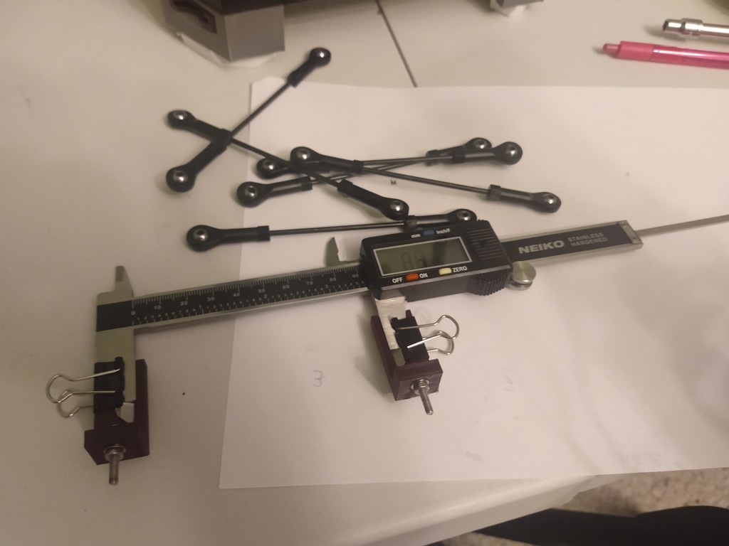
EDIT/UPDATE: I've noticed my MPMD's arms aren't perfectly parallel, so I checked the arm spacing on the carriages versus the arm spacing on the effector. This can cause a slight nozzle/effector tilt as you move farther from the bed's center. Mine is off by about 1mm, so I should be able to address it easily with 0.5mm thick M3 washers. Make sure to continue using M3 lock washers on either side of the arm joints. The purpose of this tutorial is to ensure all delta arm lengths are the same on the Monoprice Mini Delta 3D Printer. Relevant Links: 1. YouTube Tutorial for this part: https://youtu.be/GYoeg-HAw0I 2. The tool and tutorial are based on Dennis's post here: https://www.facebook.com/groups/mpminideltaowners/permalink/2370343116314494/ 3. Full Calibration Guide: https://www.reddit.com/r/mpminidelta/comments/bzm1s2/updated_mpmd_calibration_guide_and_faq/ In Dennis's original tutorial, he removed the heads from ~3mm nails and glued them to pieces of angled aluminum. I made a 3D printable version because I don't have angled aluminum or the tools to easily cut metal. The embedded caliper tool should fit a Neiko Digital Caliper (0-150mm). I also included some generic brackets which you could attach to any calipers using binder clips. You will need M3 screws, nuts, and washers. I used binder clips to hold the part securely on the calipers. BEFORE STARTING: 1. To my knowledge, very few people do this to their MPMD. 2. If all that you're doing is printing trinkets, then you probably should not care about this. 3. There are some more basic dimensional accuracy calibrations you can try before going down this rabbit hole. WHY DOES THIS ALIGNMENT MATTER? 1. Lots of math, aka Delta Kinematics, are done to tell your printer how to move. 2. One of the assumptions that the math makes is that all arms are the same length. 3. Arm length has a very direct impact on dimensional accuracy. 4. It also can affect bed leveling. 5. Do not expect it to solve all of your problems. 6. There are many alignments/calibrations that can help your printer. WHO SHOULD CARE? 1. If you have had to replace any of your arms, you should probably double check this. 2. If you are trying to improve dimensional accuracy, this is a good alignment, but you should watch my basic calibration video first. 3. Overachievers should care, but take note that there are many other upgrades/alignments that I think should take priority over this. YOU SHOULD KNOW: 1. The main goal is to have all arms measure to the same length. 2. Arms are measured from hole-center to hole-center. 3. The actual arm measurement (M665 L) just needs to be close enough for software calibration to handle the rest. 4. The arm joint holes are slightly larger than the M3 screws that go through them. 5. The arm joint holes are not the same diameter on both ends. 6. The arm joint holes are not the same diameter from joint-to-joint or arm-to-arm. Instructions for making arms the same length: 1. Measure the arms with the caliper tools by placing the arm onto the M3 screws, sliding it all the way to the nut. 2. Measure the arm by both compressing and stretching the calipers. Take the average of these two measurements. Double check your measurements several times. 3. You can adjust the arms by sliding nails/pins through the ball joints and twisting it like a turnbuckle. 4. You can optionally use the included spreadsheet to help with calculations. 5. The actual number in M665 L does not have to be perfect, just close. You will need to find the right M665/M666 combo for your machine via software calibration after the hardware adjustments. It should be in the ballpark of the stock 120.80 mm M665 L parameter unless your goal was to change the arm length for other reasons.
With this file you will be able to print MPMD Arm Measurement Tool and Tutorial with your 3D printer. Click on the button and save the file on your computer to work, edit or customize your design. You can also find more 3D designs for printers on MPMD Arm Measurement Tool and Tutorial.