MUSCLE v2.0 - bowden configuration for LONGER &CREALITY printer
thingiverse
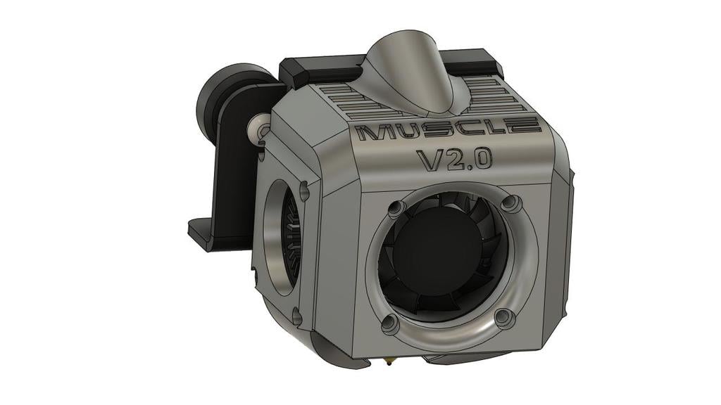
ITA-ING MUSCLE v2.0 AGGIORNAMENTO BODY: .BODY SENZA LED INTERNI .BODY PER ENDER 3 .BODY PER ENDER 3 V2 AGGIORNAMENTO CON BLThouch, ABL probe, ventola frontale 4020 nella descrizione trovate le specifiche dopo il simbolo >> IMPORTANTE : LEGGERE TUTTE LE SPECIFICHE DI MONTAGGIO IMPORTANTE 2: PRIMA DI AVVIARE LA STAMPA CON MUSCLE v2.0 CONTROLLATE CHE NON VADA AD IMPATTARE CON LO SCHERMO (SPECIE IN LK4PRO, ALFAWISE U30PRO), IN CASO POSIZIONATE UNO SPESSORE DIETRO LE VITI DELLO SCHERMO. per dubbi o domande potete contattarmi anche nelle mie pagine facebook e instagram https://www.facebook.com/3d.redlab https://www.instagram.com/3d.redlab/ se stamperete il mio progetto, taggatemi nei vostri post e mostratemi la vostra versione. questo è un fanduct progettato per utenti longer e alfawise. Ha una grande capacità di raffreddamento, derivata dalla precedente versione, la v1.0 ma decisamente migliorato. Migliorato di molto l'impatto estetico. Un nuovo design e nuove funzionalità. Nessun cavo in vista e un uscita superiore per i cavi aiuta a mantenere un disegno più pulito. Dotato di slot per inserimento led da 6mm di diametro, che creano una luce ambiente leggera attorno alla zona di stampa, ma non diretta. ci sono due versioni della copertura frontale. Una di esse ha la predisposizione per una striscia led aggiuntiva, che andrà ad illuminare precisamente la zona di stampa. La striscia led deve obbligatoriamente essere di 8 millimetri di larghezza, la lunfgezza dipemde dal taglio del led, ma di norma è 5 centimetri ogni parte separabile. Inoltre nella copertura frontale con predisposizione per striscia led è già previsto lo spazio per far passare i cavi a destra o sinistra. STAMPA: la stampa delle varie parti non sarà complicata, occorrerà usare però i supporti. Ma ho fatto in modo che lo stesso tipo di supporto vada bene per ogni componente. Inoltre sono già disposti nel lato migliore per la stampa. Consiglio di utilizzare ultimaker cura come slicer, ed impostare i supporti ad albero (solo contatto con il piano di stampa), “angolo ramo supporti ad albero” 10°, “angolo di sbalzo del supporto” 30°. il resto dei valori di supporto potete lasciarli di default. Consiglio un layer di almeno 0.2 mm inferiore. La cover frontale per un miglior impatto visivo potete stamparla a layer più basso. ASSEMBLAGGIO: dopo la stampa fate particolare attenzione ad eventuali eccessi di filamento nella zona che andrà a contatto con le ventole, soprattutto nella cover frontale e nelle laterali. In caso di eccesso rimuovete il materiale. Le due cover laterali hanno delle piccole sedi (dove poi passeranno le viti) in caso la vostra stampa non sia precisa, e le ventole forzino durante l'ingresso, dovrete consumare leggermente i spigoli di quelle sedi (o eliminare una piccola parte con un cutter) io consiglio di montare prima le ventole nelle cover, e poi di applicare le cover al body principale, stando attenti a non far rimanere i cavi in mezzo alle varie parti. Per le ventole laterali ci sono dei passaggi obbligati per i cavi, data la loro posizione, non avrete problemi a capire quali siano. La ventola frontale necessita di essere montata con i cavi in alto a destra (vista da davanti). REPARTO ELETTRICO: l'impianto elettrico è simile alla versione v1.0 le due ventole laterali andranno collegare in parallelo quindi, collegare i due cavi rossi tra di loro, in seguito collegare i due cavi neri tra di loro, in modo da avere un unica estremità per le due ventole, 1 cavo rosso (+) e un cavo nero (-) unire questi cavi ai rispettivi colori dei cavi derivati dalla scheda, per raffreddamento filamento. Consiglio di tagliare i cavi abbastanza lontani da hotend, e montare degli spinotti a due pin, in modo che risulti di facie montaggio. Alla ventola frontale andranno collegati i cavi dei led se si intende montarli. Stesso procedimento descritto sopra. Collegare insieme tutti i cavi rossi (ventola, 2 led interni, striscia led frontale) in modo da avere un unica estremita. Stesso per i cavi neri, collegarli insieme in modo da avere una sola estremità. Ora collegare il cavo rosso (+) e il cavo nero (-) ai rispettivi colori provenienti dalla scheda, per raffreddamento hotend. Consiglio di tagliare i cavi abbastanza lontani da hotend, e montare degli spinotti a due pin, in modo che risulti di facie montaggio. NB.1: i led andranno saldati al cavo della ventola solo dopo l'installazione dei led nella propria sede. NB.2: isolare sempre le saldature dei cavi con guaine termo restringenti. Se avete difficoltà a realizzare saldature, o avete dei dubbi, rivolgetevi ad un esperto. MONTAGGIO: prima di eseguire il montaggio nella stampante consiglio di assemblare i pezzi tra loro, e valutare che tutto vada bene, in modo da facilitare il montaggio poi. Prima di tutto rimuovere hotend e farlo passare dentro il body dalla parte superiore. Portare il body più in alto lungo il tubo in ptfe e i cavi, e rimontare hoten. (altrimenti si può scollegare il tubo in ptfe, sonda di calore e termistore dall'hotend, e rimontarle in seguito. ps. Prima di montare le cover laterali) Inserire il MUSCLE BODY dall'alto, in modo da far entrare la sede lungo la parte alta della piastra. Controllare l'allineamento dei fori di montaggio (si useranno solo i due più bassi) e utilizzare le viti originali per fissare il body. Inserire le ventole nelle rispettive cover. Montare le due cover laterali, e serrare con viti M3x16 ( viti con testa non svasata) *se avete smontato tubo in ptfe, sonda e termistore, ora è il momento di rimontarle. Montare cover frontale (tenendo in posizione corretta i cavi al suo interno) e serrare con 2 viti M3x25 (viti con testa non svasata) nella parte sopra, e 2 viti M3x20 nella parte bassa (viti con testa non svasata). Ora collegate i cavi agli spinotti (o se non li avete montati, saldate i cavi), e portate il tubo passacavi fino a dentro l'asola predisposta. >>specifiche per i nuovi componenti dell'aggiornamento. I valori di stampa consigliati rimangono gli stessi della descrizione. Solo --MUSCLE v2.0-BLthouch inferior support-- non habisogno di supporti durante la stampa. Per il montaggio dei supporti per sensori di livellamento sarà necessario stampare una nuova cover laterale sinistra, a seconda tra blthouch o ablprobe troverete i due file per la cover laterale. L'assemblaggio del supporto per ABLprobe avviene con 2 viti M3x20, le altre due viti della cover laterale sono sempre M3x16. L'assemblaggio del supporto (superiore ed inferiore) per blthouch avviene tramite 4 viti M3x20. La distanza tra nozzle e blthouch è : X47.004 mm Y15.594 mm per la stampa e il montaggio delle due nuove versioni delle cover laterali, e la cover frontale con alloggio ventola 4020, leggere la descrizione generale, seguendo i vari step indicati. LINK MATERIALI Led 6mm 24v interni body https://a.aliexpress.com/_uhjXGR https://www.amazon.it/dp/B088D1M47R/ref=cm_sw_r_cp_apa_glt_i_WDAB8FPSEBKA2RATTHKT?_encoding=UTF8&psc=1 Striscia led larga 8mm 24v https://a.aliexpress.com/_ujdoSB https://www.amazon.it/dp/B07T2L3K6D/ref=cm_sw_r_cp_apa_glt_i_ZPH4P13TC7PJCW1XGHR8 Ventola frontale 24v https://www.amazon.it/dp/B07CV6VTWB/ref=cm_sw_r_cp_apa_glt_i_JXRCXVW6JH9JJ6KGMHD7 Ventole laterali 24v https://www.amazon.it/dp/B08CY3VCQW/ref=cm_sw_r_cp_apa_glt_i_GH6HCPWMFQKVNQFE0RCP?_encoding=UTF8&psc=1 i miei progetti li troverete sempre qui, e altrove, rigorosamente gratuiti. ma se vorrete lasciarmi un piccolo incentivo ne sarò davvero felice https://paypal.me/manuelveschi …................................................................................................................................................ MUSCLE v2.0 UPDATE BODY: .BODY WITHOUT LED .BODY FOR ENDER 3 .BODY FOR ENDER 3 V2 UPDATE WITH BLThouch, ABL probe, 4020 front fan in the description you will find the specifications after the symbol >> IMPORTANT: READ ALL MOUNTING SPECIFICATIONS IMPORTANT 2: BEFORE STARTING PRINTING WITH MUSCLE v2.0, CHECK THAT IT DOES NOT IMPACT THE SCREEN (ESPECIALLY IN LK4PRO, ALFAWISE U30PRO), IF YOU PLACE A THICKNESS BEHIND THE SCREW SCREWS for doubts or questions you can also contact me on my facebook and instagram pages https://www.facebook.com/3d.redlab https://www.instagram.com/3d.redlab/ if you print my project, tag me in your posts and show me your version. this is a fanduct designed for longer and alfawise users. It has a large cooling capacity, derived from the previous version, v1.0 but definitely improved. Much improved the aesthetic impact. A new design and new features. No cables in sight and a superior cable exit help maintain a cleaner design. Equipped with a slot for inserting 6mm diameter LEDs, which create a light ambient light around the printing area, but not direct. there are two versions of the front cover. One of them is designed for an additional LED strip, which will precisely illuminate the printing area. The led strip must necessarily be 8 millimeters wide, the length depends on the cut of the led, but as a rule each separable part is 5 centimeters. Furthermore, in the front cover with predisposition for led strip there is already space for passing the cables to the right or left. PRINT: the printing of the various parts will not be complicated, but it will be necessary to use the supports. But I made sure that the same type of support works for every component. They are also already arranged on the best side for printing. I recommend using ultimaker cura as a slicer, and set the tree supports (only in contact with the print bed), “branch angle of tree supports” 10 °, “support cantilever angle” 30 °. the rest of the support values you can leave them as default. I recommend a layer of at least 0.2 mm lower. The front cover for a better visual impact you can print it at a lower layer. ASSEMBLY: after printing, pay particular attention to any excess filament in the area that will come into contact with the fans, especially in the front cover and on the sides. In case of excess, remove the material. The two side covers have small seats (where the screws will then pass) in case your print is not precise, and the fans force during the entry, you will have to slightly wear the edges of those seats (or remove a small part with a cutter ) I recommend that you first mount the fans in the covers, and then apply the covers to the main body, being careful not to let the cables remain in the middle of the various parts. For the side fans there are mandatory passages for the cables, given their position, you will have no problem understanding which ones they are. The front fan needs to be mounted with the cables at the top right (seen from the front). ELECTRICAL DEPARTMENT: the electrical system is similar to version v1.0 the two side fans will be connected in parallel then, connect the two red cables together, then connect the two black cables together, so as to have a single end for the two fans, 1 red cable (+) and a black cable (-) join these cables to the respective colors of the cables derived from the board for filament cooling. I recommend cutting the cables far enough away from the hotend, and fitting two-pin plugs, so that it is easy to fit. The LED cables must be connected to the front fan if you intend to mount them. Same procedure as described above. Connect all the red cables together (fan, 2 internal LEDs, front LED strip) in order to have a single end. Same for the black cables, connect them together so that you have only one end. Now connect the red cable (+) and the black cable (-) to the respective colors coming from the board, for hotend cooling. I recommend cutting the cables far enough away from the hotend, and fitting two-pin plugs, so that it is easy to fit. NB.1: the LEDs will be soldered to the fan cable only after the installation of the LEDs in their seat. NB.2: always insulate the welds of the cables with thermo-shrinking sheaths. If you have difficulty in making welds, or if you have any doubts, contact an expert. ASSEMBLY: before carrying out the assembly in the printer I recommend to assemble the pieces together, and evaluate that everything is fine, in order to facilitate the assembly then. First of all remove the hotend and pass it inside the leotard from the top. Bring the body higher along the PTFE tube and cables, and reassemble the hoten. (otherwise you can disconnect the PTFE tube, heat probe and thermistor from the hotend, and reassemble them later. ps. Before mounting the side covers) Insert the MUSCLE BODY from the top, so that the seat fits along the top of the plate. Check the alignment of the mounting holes (only the lower two will be used) and use the original screws to secure the body. Insert the fans into their respective covers. Mount the two side covers, and tighten with M3x16 screws (screws with non countersunk head) * if you have disassembled the PTFE tube, probe and thermistor, now is the time to reassemble them. Mount the front cover (keeping the cables in the correct position inside) and tighten with 2 M3x25 screws (screws with non-countersunk heads) in the upper part, and 2 M3x20 screws in the lower part (screws with non-countersunk heads). Now connect the cables to the plugs (or if you have not mounted them, solder the cables), and bring the cable duct up to the provided slot. >> specifications for the new components of the update. The recommended print values remain the same as the description. Only --MUSCLE v2.0-BLthouch inferior support-- does not need media when printing. To mount the supports for leveling sensors it will be necessary to print a new left side cover, depending on between blthouch or ablprobe you will find the two files for the side cover. The assembly of the support for ABLprobe takes place with 2 M3x20 screws, the other two screws of the side cover are always M3x16. The assembly of the support (upper and lower) for blthouch is done using 4 M3x20 screws. The distance between nozzle and blthouch is: X47.004 mm Y15.594 mm for printing and assembly of the two new versions of the side covers, and the front cover with fan housing 4020, read the general description, following the various steps indicated. LINK MATERIALS Led 6mm 24v internal body https://a.aliexpress.com/_uhjXGR https://www.amazon.it/dp/B088D1M47R/ref=cm_sw_r_cp_apa_glt_i_WDAB8FPSEBKA2RATTHKT?_encoding=UTF8&psc=1 8mm wide 24v led strip https://a.aliexpress.com/_ujdoSB https://www.amazon.it/dp/B07T2L3K6D/ref=cm_sw_r_cp_apa_glt_i_ZPH4P13TC7PJCW1XGHR8 24v front fan https://www.amazon.it/dp/B07CV6VTWB/ref=cm_sw_r_cp_apa_glt_i_JXRCXVW6JH9JJ6KGMHD7 24v side fans https://www.amazon.it/dp/B08CY3VCQW/ref=cm_sw_r_cp_apa_glt_i_GH6HCPWMFQKVNQFE0RCP?_encoding=UTF8&psc=1 you will always find my projects here, and elsewhere, strictly free. but if you want to leave me a little incentive I'll be really happy https://paypal.me/manuelveschi
With this file you will be able to print MUSCLE v2.0 - bowden configuration for LONGER &CREALITY printer with your 3D printer. Click on the button and save the file on your computer to work, edit or customize your design. You can also find more 3D designs for printers on MUSCLE v2.0 - bowden configuration for LONGER &CREALITY printer.