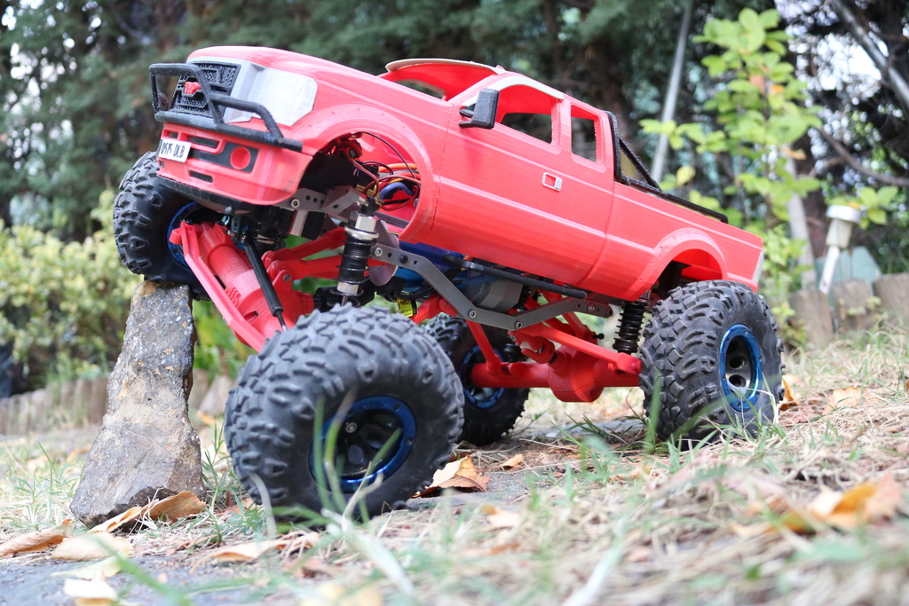
MyRCCar 1/10 MTC Rigid Axles: 4 different axle wides, 8 different CVDs, wheelbases from 290 to 330mm and universal shafts
thingiverse
After listening to the crowd, I decided to create this new work about RC car styles. When I designed MTC Chassis, I knew I wanted to build a hybrid - an rc car with independent suspension in the front and rigid axle in the back. But I went further. Now you can use some of the original MTC Chassis printed parts to build a Monster Truck/Crawler with rigid axles, 4 link suspension system, and universal shafts. Hey! No video yet, but subscribe or visit my Youtube Channel to see previous videos from the MTC Chassis and Pickup. I'm tired right now to write up specific instructions, so this publication is just for experts who can receive instructions directly from the design shapes and logic patterns. ### The Axles: As you can see, there are 3 different center parts for the axles. This will give you 3 different widths for your axles - you just have to choose. There's also a wider one using the long axle and the "long C-Hubs" or "long rear fixed blocks". You can use: * 4 different CVDs with the long axle plus 2 more with the long c-hubs * 2 different CVD combinations with the medium axle * 2 different CVDs with the small axle ### The Steering: There are 2 different C-Hubs - the long one is only for HSP 108015 and HSP 188015. There are also 4 different Steering Blocks, the same types than in all MyRCCar publications. You'll need 6 different Rear Fixed Blocks, 2 of them longer for HSP 108015 and HSP 188015. And 4 different steering plates or "bars", one for each axle width - XL, L, M, and S. ### The links: These links are Print in Place ball joint articulated. I use to print with -0.02 horizontal expansion to get the correct results, this time i printed them with -0.03. Take a look at the photos and drawings to see how they work. You'll need to assemble them carefully to avoid any issues. ### The fake SST Fixed Differential: Just two parts that must be joined with 2 M3x8mm countersunk screws. Then use the normal adaptors and 12x18x4 bearings for your SST diff and mount the fake fixed diff into the gearbox. ATTENTION: The position of the motor is very important, and I have designed it to work with the gearbox and 14T pinion for the motor attacking a 28T gear. If this parameters changes then the motor can touch the universal shaft or the lower links, the space is very important in this build! ### Other Things: * I created a Battery Box for the standard top cover. I mounted it in the back but can be mounted in the front part too. * You must use the front platform inverted in vertical and front/back in combination with links_FrontPlatformHolder. You don't need rear platform * You can put ESC and reciever over front platform if you mount the Battery Box in the back Please analyze the info here and in the photos and drawings, the same than in previous MyRCCar projects and MyRCCar Group to solve great part of your doubts.
With this file you will be able to print MyRCCar 1/10 MTC Rigid Axles: 4 different axle wides, 8 different CVDs, wheelbases from 290 to 330mm and universal shafts with your 3D printer. Click on the button and save the file on your computer to work, edit or customize your design. You can also find more 3D designs for printers on MyRCCar 1/10 MTC Rigid Axles: 4 different axle wides, 8 different CVDs, wheelbases from 290 to 330mm and universal shafts.