NE555 Demo PCB
thingiverse
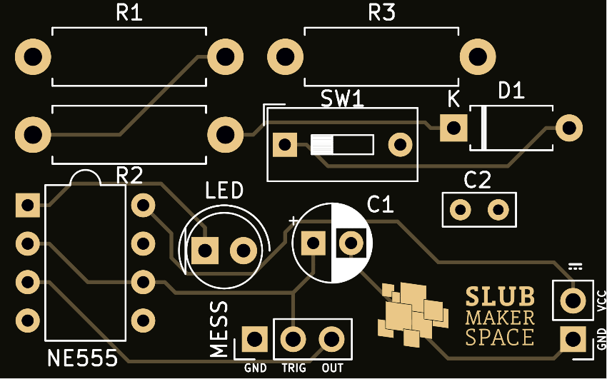
This simple blinking circuit was designed in [KiCAD](https://kicad.org) to demonstrate how to use an oscilloscope. It is based on the integrated circuit NE555. The autorouting was created with [Freerouting](https://freerouting.org/) and was adapted manually. Dimensions: 40 mm × 25 mm ###Values and Components The selected components lead to characteristic values of the circuit. Other components are possible and result in different characteristics. The LED's and the NE555's maximum voltage have to be observed. The following values characterise the circuit in its planned state: ‧ Supply voltage: 5 V DC ‧ Switching between duty factor > 50 % and < 50 % possible with DIP-Switch. (On means < 50 %.) ‧ Frequency: 1.505 Hz | 2.257 Hz ‧ Duty Cycle: 66.667 % | 50 % The following components were used: ‧ R1: 68 kΩ ‧ R2: 68 kΩ ‧ R3: 330 Ω ‧ LED: rot ‧ C1: 4.7 µF ‧ C2: 10 nF ‧ D1: 1N4148 ###Usage The power supply is connected in the right lower corner next to the logo. The polarity should be observed carefully! Then the LED starts blinking. The oscilloscope can be connected to the three MESS-Pins on the lower side. One ground clamp is connected to GND (left). Two test prods are connected to TRIG and OUT. Make sure to avoid a short circuit. Consider using some extra jumper wire. With the correct settings for the oscilloscope you should be able to recreate the picture as shown here. <sub>License: [CC-BY](https://creativecommons.org/licenses/by/4.0/) SLUB Dresden | Carsten Pietzsch</sub> *** Zur Messung mit dem Oszilloskop wurde eine einfache Blinkschaltung in [KiCAD](https://kicad.org) entworfen. Die Schaltung basiert auf dem Integrierten Schaltkreis NE555. Das Autorouting wurde mit [Freerouting](https://freerouting.org/) durchgeführt und händisch angepasst. Dimension: 40 mm × 25 mm ###Kennwerte und Bauelemente Die ausgewählten Bauelemente führen zu bestimmten Kennwerten der Schaltung. Andere Bauelemente sind möglich und bewirken andere Eigenschaften der Schaltung. Dabei müssen die Spannungsgrenzen von NE555 und LED eingehalten werden. Folgende Kennwerte charakterisieren die Schaltung im geplanten Zustand: ‧ Spannungsversorgung: 5 V DC ‧ Umschaltung zwischen Tastverhältnis > 50% und < 50 % mittels DIP-Schalter möglich (ON bedeutet < 50 %) ‧ Frequenz: 1,505 Hz | 2,257 Hz ‧ Tastverhältnis: 66,667 % | 50 % Folgende Bauelemente kommen dabei zur Anwendung: ‧ R1: 68 kΩ ‧ R2: 68 kΩ ‧ R3: 330 Ω ‧ LED: rot ‧ C1: 4,7 µF ‧ C2: 10 nF ‧ D1: 1N4148 ###Verwendung Der Anschluss der Stromversorgung erfolgt rechts unten neben dem Logo. Dabei ist unbedingt die Polarität zu beachten! Anschließend beginnt die LED zu blinken. Das Oszilloskop lässt sich an den 3 MESS-Pins unten mittig anschließen. Eine Erdungsklemme wird an GND (links) angeschlossen. Die beiden Messspitzen werden an TRIG und OUT angeschlossen. Dabei ist zu beachten, dass kein Kurzschluss zwischen den Pins erzeugt wird! Anschließend ergibt sich bei korrekter Einstellung des Oszilloskops in etwa das Bild im Anhang. <sub>Lizenz: [CC-BY](https://creativecommons.org/licenses/by/4.0/) SLUB Dresden | Carsten Pietzsch</sub>
With this file you will be able to print NE555 Demo PCB with your 3D printer. Click on the button and save the file on your computer to work, edit or customize your design. You can also find more 3D designs for printers on NE555 Demo PCB.