NEMA 17 10:1 Cycloidal Drive
thingiverse
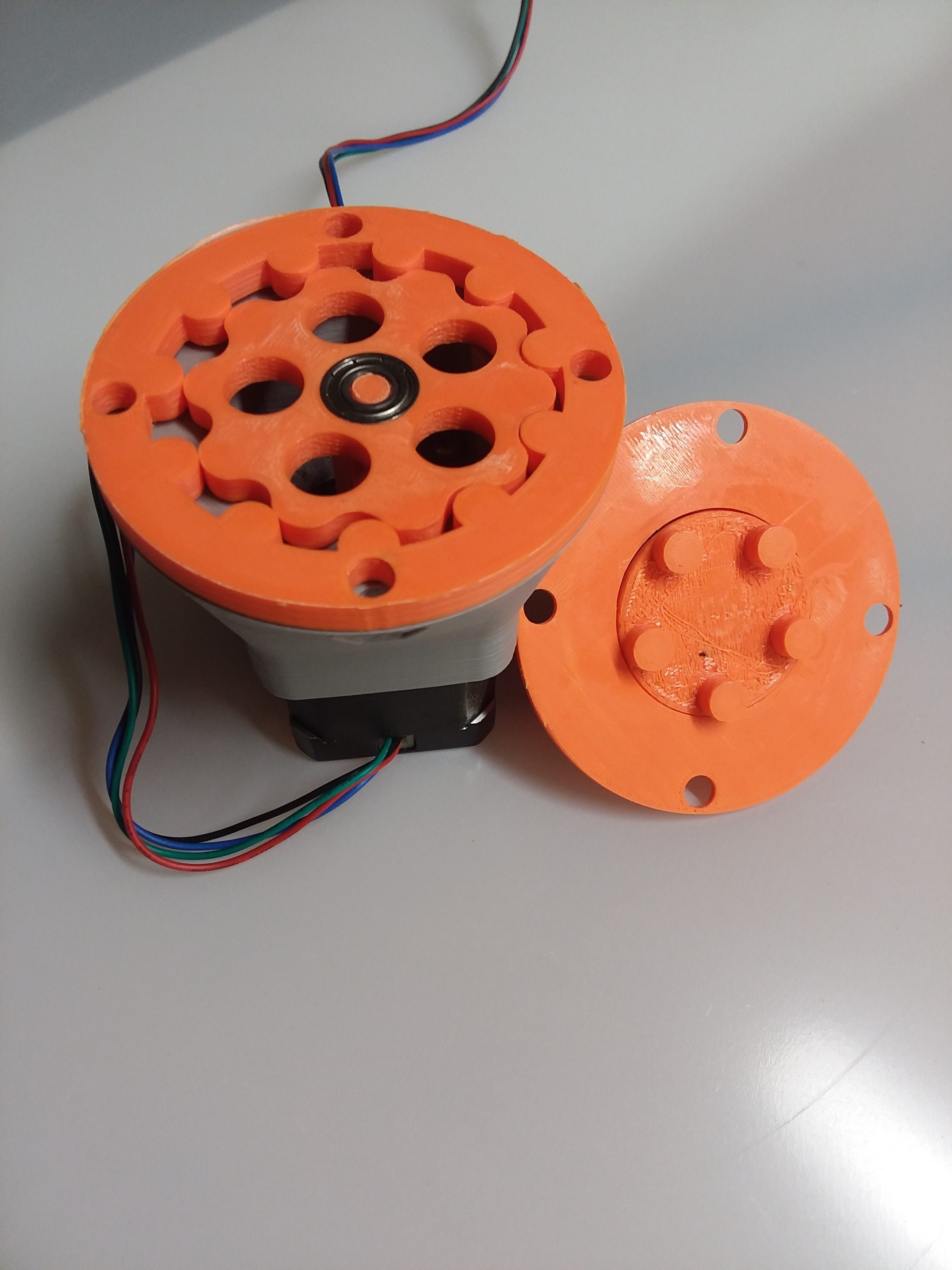
A functional 3D printed 10:1 cycloidal drive for the NEMA 17 stepper motor. Customizable by swapping out a couple components (rotor, input shaft, middle ring) allowing for quick reduction modifications even if the parts aren't pre-printed. The larger components (base, output shaft, top) can be reused with different reductions. This design requires minimal, common hardware you may have on hand as listed below: + 4x Housing Bolts 1/4" x 3/4" (Holes can be modified or drilled out to fit M7) + 4x Housing Bolt Nuts 1/4" + 4x Base Screws M3 x 6mm + 28x BBs 6mm (Optional works well without) + 1x Bearing 6mm ID x 15mm OD x 5mm Width The relatively large package size is a consequence from using 3D printed shafts that experience high stress but another advantage is the printer's tolerance can be relatively large. The most frequent failure point is the input shaft. Through testing the rpm output is 10 times lower than input and the torque capacity is 3 times greater than a standard NEMA 17. The model was created in Fusion 360 using a script written by mawildoer that can be found here: https://github.com/mawildoer/cycloidal_generator When the model was designed Fusion 360 did not have the capability to sketch an equation driven curve through its GUI but does have the ability through the API and mawildoer did just that. A technical discussion and equations describing how to generate the rotor design can be found here: https://doi.org/10.1515/ama-2016-0022 The Fusion 360 files can be downloaded for use from the following link: https://a360.co/3cicRs2 **Assembly** 1. Press the bearing onto the input shaft 2. Slide the input shaft onto the NEMA 17 motor shaft making sure to align the D shaft profile. 3. Attach the NEMA 17 to the base using the M3 machine screws 4. Check if the shaft and bearing are positioned correctly by visually making sure the bearing sticks out of the base and the bearings is relatively flush to the outer surface of the base 5. Press the rotor onto the bearing till it meets the outer surface of the base 6. Place the middle ring around the rotor and turn the middle ring till the bolt holes line up on the outside perimeter 7. Place the output shaft, pins down, onto a level table and fill the BB tracks with 6mm BBs 8. Place the top cover over the output shaft carefully to not knock out the BBs and once against the BBs press down to lock the BBs in the top cover. The two parts should not be easily separable 9. Place the top cover assembly over the rotor aligning output shaft pins with the holes in the rotor and twist the top cover to align the perimeter bolt holes 10. Fasten the housing together using 1/4" bolts and nuts Printing Notes + Printing in Low resolution increases layer height which increases the overall part strength. + Pictured is orange ABS and gray PLA due to limited ABS supply Unless mentioned layer height of 0.3mm + Base: Perimeter: 3 Infill: 0.2 and use support Orient circular side down + Input Shaft: Perimeter: 4 Infill: 0.2 Layer height 0.1mm and use support Orient input shaft axis parallel to build plate plane to increase strength + Rotor: Perimeter: 3 Infill: 0.2 Orient flat + Ring: Perimeter: 3 Infill: 0.2 Orient flat + Output shaft: Perimeter: 4 Infill: 0.2 and use support Orient output shaft axis parallel to build plate plane to increase strength + Top: Perimeter: 2 Infill: 0.2 and use support Orient larger circular side down
With this file you will be able to print NEMA 17 10:1 Cycloidal Drive with your 3D printer. Click on the button and save the file on your computer to work, edit or customize your design. You can also find more 3D designs for printers on NEMA 17 10:1 Cycloidal Drive.