Nerf Gun V2
thingiverse
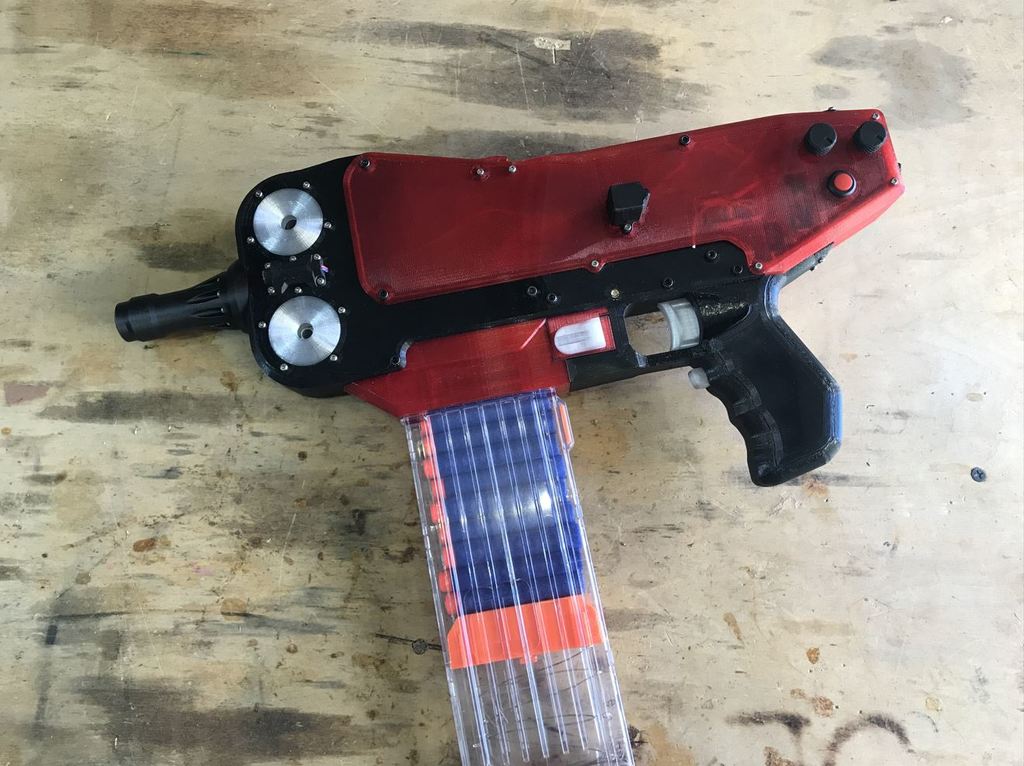
This is the nerf annihilator. An absolute beast in all regards, with two high speed 2206 brushless motor at the heart of its massive flywheel cage, and a slim, ergonomic design to boot. Capable of firing 15 rounds per second, and ludicrous muzzle velocities, the mere use of this revolutionary new weapon in nerf fights has been ruled a war crime by the International Criminal Court. And now, you, the wielder of this otherworldly contraption, will strike down your enemies from afar, your deadly darts guided by the built in laser, and both the fire rate of muzzle velocity fully adjustable at the whim of your mercy. Yes, should you succeed in constructing this behemoth, your greatest challenge will no longer be conquering the mere mortals that cower at your feet, but keeping your own ego from growing beyond all proportion and blowing up like a hydrogen filled blimp. Infomercial dialogue aside, here follows everything you need to know to build this thing. Every single piece of this blaster is held in place by heat set nuts and screws. You will need a variety of M2 screws, ranging from 6mm in length to 30mm. You will need M3 screws ranging from 8mm in length to 40mm. You will also require at about 50 of both M2*4mm heat set nuts and M3*4 heat set nuts. You will also require about 10 centimeters of 2mm diameter metal rod and 6 centimeters of 3mm metal rod, along with four 6*3mm magnets and four 3*2m magnets. Lastly, three springs with an inner diameter slightly greater than 3mm and a length of at least 25mm. With this, you will be able to but together every part. As for the instructions of putting everything together, I never actually filmed the assembly process, but I will include the original Fusion 360 file so that you can see how everything fits together and so you can change the design however you want if you feel like it. If you have any questions or confusion, I'll help clear it up, just comment here or on the reddit page. Reddit: https://www.reddit.com/r/3Dprinting/comments/wntu82/im_back_guys_with_the_nerf_annihilator/ Not for the parts list. Some of these are pretty generic, so I won't put links for everything, and I wont include the bits that I mentioned above. Ah well. Here goes. PARTS LIST 2x - 2206 (or 2207) 2750KV brushless motor 2x - 35A brushless ESC 2x - N30 single shaft 580 rpm brushed DC motor (https://www.aliexpress.com/item/2261799822480529.html?spm=a2g0o.order_list.0.0.47c81802eCfcYr&gatewayAdapt=4itemAdapt) *Note: The shaft should be perpendicular, not parallel, to the motor. 1x - MOS motor driver (https://www.amazon.com/gp/product/B07D1W6VFS/ref=ppx_yo_dt_b_search_asin_title?ie=UTF8&psc=1) *Note: should be compact and be able to handle at least 30 volt and 5A so this is a very good option) 2x - Voltage boost Module (https://www.amazon.com/Eiechip-Voltage-Regulator-Converter-Module/dp/B07RNBJK5F/ref=sr_1_1_sspa?keywords=voltage+boost+module&qid=1660433236&sr=8-1-spons&psc=1&spLa=ZW5jcnlwdGVkUXVhbGlmaWVyPUEzREVESlVDRFhDWFY2JmVuY3J5cHRlZElkPUEwMDYyODEwM0tPRzFONFcxVE9FViZlbmNyeXB0ZWRBZElkPUEwNDc0NzM0MldaNURHRVJGOExVTSZ3aWRnZXROYW1lPXNwX2F0ZiZhY3Rpb249Y2xpY2tSZWRpcmVjdCZkb05vdExvZ0NsaWNrPXRydWU=) *Note: must be compact so I highly recommend this option. *Note#2: Set them to 20V. 1x - Buck voltage regulator (https://www.amazon.com/Regulator-Adjustable-Converter-Electronic-Stabilizer/dp/B07PDGG84B/ref=sr_1_1_sspa?crid=1VCQR8ZXNAWKC&keywords=voltage+buck+module&qid=1660433334&sprefix=voltage+buck+module%2Caps%2C47&sr=8-1-spons&psc=1&spLa=ZW5jcnlwdGVkUXVhbGlmaWVyPUE2VjJPTlQyVE9CUUUmZW5jcnlwdGVkSWQ9QTAzNzMyNDQxS1FWMTg3T1lSREFaJmVuY3J5cHRlZEFkSWQ9QTA0ODg5MjAzSldQMzE0Sk9CQk5HJndpZGdldE5hbWU9c3BfYXRmJmFjdGlvbj1jbGlja1JlZGlyZWN0JmRvTm90TG9nQ2xpY2s9dHJ1ZQ==) *Note: Set to 5V 3x - 18650 Li-ion Batteries (Amp rating should be 20A or greater, such as these: https://liionwholesale.com/collections/batteries/products/bak-n18650cnp-18650-30a-flat-top-2500mah?variant=39353194283077) ~ 30 cm - 14 gauge silicone wire ~ 1 meter - 22 gauge silicone wire ~ 2 meter - 28 gauge silicone wire 1x - Arduino Nano microcontroller 2x - potentiometer (I used these: https://www.amazon.com/dp/B071ZX42VV/?coliid=I3K8IBNR2SO4NV&colid=19TEZ8IX636UV&psc=1&ref_=lv_ov_lig_dp_it) 1x - 16mm illuminated latching power button (https://www.aliexpress.com/item/2251832770316650.html?spm=a2g0o.order_list.0.0.4d531802MsPl4c) *Note: select the 5v voltage and the latching option. 1x - 12mm illuminated latching power button (https://www.aliexpress.com/item/3256802424511797.html?spm=a2g0o.order_list.0.0.47c81802eCfcYr&gatewayAdapt=4itemAdapt) *Note: select the 5v voltage and the latching option. 2x - mechanical relay (https://www.aliexpress.com/item/3256802895043774.html?spm=a2g0o.productlist.0.0.6bd97fe3lNB2OH&algo_pvid=aa7a549f-ba23-40aa-a157-9b93e9c43248&algo_exp_id=aa7a549f-ba23-40aa-a157-9b93e9c43248-10&pdp_ext_f=%7B%22sku_id%22%3A%2212000023964602724%22%7D&pdp_npi=2%40dis%21USD%211.34%211.31%21%21%21%21%21%402101e9d516604335183863893eb99b%2112000023964602724%21sea&curPageLogUid=Ukz8WHWfibvU) *Note: Select 5v option 1x - red dot laser diode (https://www.amazon.com/gp/product/B071FT9HSV/ref=ppx_yo_dt_b_search_asin_image?ie=UTF8&psc=1) 1x - Schottky diode, rated for at least 5A and 30 volts 1x - One pair of T-plug connectors 1x - JST 3S connector 1x - Electrolytic capacitor rated for at least 30 volt and 500 - 1000µF or so. 1x - 1000 Ohm resistor 2x - 10000 Ohm resistor 1x - momentary button switch (https://www.amazon.com/Cylewet-Momentary-Button-Switch-CYT1078/dp/B0752RMB7Q/ref=sxin_14_ac_d_mf_brs?ac_md=3-2-Q3lsZXdldA%3D%3D-ac_d_mf_brs_brs&content-id=amzn1.sym.37d5b521-1d59-436f-8d1e-f9aa8f2d7ab6%3Aamzn1.sym.37d5b521-1d59-436f-8d1e-f9aa8f2d7ab6&crid=21T2AKUONC4E8&cv_ct_cx=button+switch&keywords=button+switch&pd_rd_i=B0752RMB7Q&pd_rd_r=8ab555fd-9249-4871-89db-89261bcd0966&pd_rd_w=m3m3N&pd_rd_wg=cZF10&pf_rd_p=37d5b521-1d59-436f-8d1e-f9aa8f2d7ab6&pf_rd_r=VS48J3P9EAT25BT8KTE9&psc=1&qid=1660436322&sprefix=button+switch%2Caps%2C88&sr=1-3-8b2f235a-dddf-4202-bbb9-592393927392) *Note: It must be this kind of switch 1x - DPDT 6 Pin button switch (https://www.amazon.com/gp/product/B07PK6C6LB/ref=ppx_yo_dt_b_search_asin_image?ie=UTF8&psc=1) *Note: you must use tweezers or pliers to pluck out the curved piece of metal to turn the latching switch found at this link into a momentary one. You could try finding a switch that's momentary off the bat but I couldn't. 3x - M3*15 brass standoff END OF PARTS LIST Ah, now for the simple matter of wiring. I don't have exact wiring schematics, but I will explain what ever part does and how they interact with each other. First, you should start by wiring the three 18650 batteries into a pack. Use the female T-plug and male 3S JST connector for this. Now listen carefully. FIRST, connect the flywheels to the motors, THEN secure the motors to the flywheel cage, LASTLY, thread the motor wires through the holes in the flywheel cage and solder on the electronic speed controllers (ESCs). Make sure that the motors are wired to properly to they spin opposite each other and push darts outward, not inward. the signal wires of the ESCs will go into the Arduino Nano. The main power switch cannot handle all the power, so it will only switch power to the 5v buck regulator, which will then open the relays, which should be connected in parallel. The main power of the battery is switched by the relays, and goes into both ESCs, and into the two voltage boost modules, which should be set to around 20 to 24 volt and wired in parallel as well. Wire the output of the boost modules into the MOS motor driver, and connect the output of the MOS motor driver to the two N30 motors, maker sure that they are connected the right way so that they don't spin in the wrong direction or opposite each other. Connect the signal wire of MOS motor driver to the Arduino. Connect the capacitor and resistor across the output of the boost modules, and make sure to protect the input with the diode, as the brushless motors generate a large negative voltage when slowing down that can burn out the modules otherwise. Wire the output of the 5v regulator to the Arduino Nano, the light terminals of the 16mm power button, and to the laser diode, with the 12mm button switch switching power to the laser diode and to its own light terminals. The three wires of each of the potentiometers should be soldered to the Arduino. Lastly, both the button switch that controls the brushless motors and the button switch that controls the N30 motors should connect between the 5v pin of the Arduino and the proper input pin (to be specified later), and each of those two input pins should be connected to the GND pin of the Arduino through a 10000 Ohm resistor. Well, I think I've covered everything I could think to. Sorry if it's not the most intuitive instructions, I certainly could have prepared this better, but I suppose to confidently build this thing you'll need some prior knowledge of electronics. CODE I've included the Arduino code to make this whole thing work in the files. Here's the guide for what wire should be connected to what pin of the Arduino: - 5v positive output from regulator: 5v - 5v negative output from regulator: GND - Potentiometer that controls fire rate left wire: 5v - Potentiometer that controls fire rate middle wire: A0 -Potentiometer that controls fire rate left wire: GND - Potentiometer that controls power left wire: 5v - Potentiometer that controls power middle wire: A1 - Potentiometer that controls power right wire: GND - Both negative signal wires of ESC: GND - Both positive signal wires of ESC: 3 - Motor Rev button left wire: 5v - Motor Rev button right wire: 10 - Firing button left wire: 5v - Firing button right wire: 11 *** Don't forget to connect pin 10 to GND through a 10000 Ohm resistor and pin 11 to GND using a 10000 Ohm resistor. Aaaaaaaand that's all folks. Good luck, and Godspeed.
With this file you will be able to print Nerf Gun V2 with your 3D printer. Click on the button and save the file on your computer to work, edit or customize your design. You can also find more 3D designs for printers on Nerf Gun V2.