(New Version) Mini Talon Removable Landing Gear
thingiverse
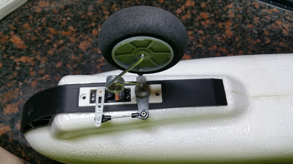
I had a few people tell me that their kit from Banggood did not include the steering arm/horn or the small collar that was needed for the inside of the shaft, so I redesigned the landing gear to eliminate both of those pieces. Now you can print everything you need to easily install landing gear onto your Mini Talon. https://youtu.be/qJZGLSQbhl0 Parts Needed: Landing gear kit from Banggood or any wire spring landing gear using M2 wire. Used for front nose gear: https://www.banggood.com/DIY-60-Level-Tail-Wheel-Bracket-Assembly-for-RC-airplane-p-908726.html Used for rear gear: https://www.banggood.com/2mm-Aluminum-Landing-Gear-Set-For-25-40-Class-Electric-RC-Airplane-p-1151154.html 2 MR128ZZ bearings for front shaft: (FastEddy is my favorite eBay seller for quality bearing in the USA shipped fast!) https://www.ebay.com/sch/i.html?_from=R40&_trksid=m570.l1313&_nkw=MR128ZZ&_sacat=0 1 Emax ES08 metal gear servo. (analog or digital): https://www.banggood.com/EMAX-ES08MA-II-12g-Mini-Metal-Gear-Analog-Servo-for-RC-Model-p-935479.html OR https://www.banggood.com/Wholesale-Emax-ES08MDII-Metal-Digital-Micro-Servo-p-68600.html 2 M3 hexagon nuts with 5.5mm (.216") flat to flat (wrench size) for front servo housing to skid. 2 1/4-20 hexagon nuts with .360" flat to flat (23/64" wrench size) for rear gear. Various M3 screws. I am not specifying the control linkage since there are so many options for this. You probably already have something that will work laying around. Specific Tools Needed: 2mm (.079") drill bit 2.5mm (.098") drill bit Number 7 (.201") drill bit M3 tap 1/4-20 tap Directions: READ THEM! Yes there's plenty of picture to help but you must do certain things that the pictures do not show... FRONT: Once you have all of your parts printed and cleaned up, press your 2 bearings into the servo housing and make sure they are fully seated. Now test fit the printed shaft, and make sure that the bottom of the shaft sits flush with the bottom of the servo housing, and that the shaft turns freely in the bearings, if not the bearings may be misaligned slightly, you can sand the shaft until you get a nice tight fit yet still be able to easily turn the shaft once inserted and sitting flush. Now remove the shaft from the servo housing and drill through the full length of the entire shaft with a 2mm (.079") drill bit to ensure a nice tight clean fit of the wire landing gear. Clean and remove any elephants foot on the bottom (bed) side of the steering horn and test fit the printed shaft into the horn. The shaft needs to fit snug but still be able to come off. Once you are satisfied with the fit, reinsert it into the servo housing and fully seat the steering horn onto the shaft. If everything is correct there will be NO up and down movement. Now using a 2.5mm (.098") drill bit carefully drill the hole where the screw goes, all the way into the shaft until you can see the drill bit. (This properly sizes and straightens the hole, do not skip this step!) Take care not to allow the steering horn to rotate onto the shaft at this point. Now run an M3 tap through this hole, but do not quite break through into the shaft hole. This will allow the screw to form the thread which will act like a nylon lock nut. Back the tap out, clean it off then re-thread it once again for a nice clean threaded hole. Now you might want to run that 2mm (.079") drill bit through the length of the shaft once more time to remove any shavings. On your wire landing gear, cut the wire that goes into the shaft down so that you have about 32mm (1.25") of STRAIGHT wire. Once this is done, you can insert the wire landing gear into the shaft and LIGHTLY tighten it down using a 10mm long M3 screw. Do not over tighten this screw, you will strip the threads if you go to much! (Just tight enough to prevent the wire landing gear from spinning inside the shaft) Now test fit the front skid and cut the foam out like you see in the picture, then glue the front skid into place using either E6000 or UhuPor and let it set up. Once the glue has setup you can install the servo housing with the landing gear in place and fasten using self taping or M3 screws. REAR: There's 2 choices for attaching the rear gear to the belly mount. In my case I used the hexagon nut mount. OR Choose the drill (#7/.201") and tap (1/4-20) version. DO NOT GO ANY BIGGER, remember this is not a solid piece! (another reason to have at least 5 vertical shells!) In both cases, USE NYLON SCREWS to hold gear to belly mount! This will allow them to break in a severe landing rather than ripping the gear off the plane! You will need to drill 2 new holes slightly larger than your nylon screws, and 2.75" apart on your aluminum gear (1.375" from center) See notes below if your screw heads hit the curved part of the gear Gluing pieces to fuselage: Once you have everything fitted and are satisfied, use either E6000, or Uhu Por to glue the rear belly mount into place and install your landing gear. Note: I changed out the wheels that came with my gear for larger wheels since I use a grass runway.
With this file you will be able to print (New Version) Mini Talon Removable Landing Gear with your 3D printer. Click on the button and save the file on your computer to work, edit or customize your design. You can also find more 3D designs for printers on (New Version) Mini Talon Removable Landing Gear.