No-Slop linkage hardware for TH Crack Lite series airplanes
thingiverse
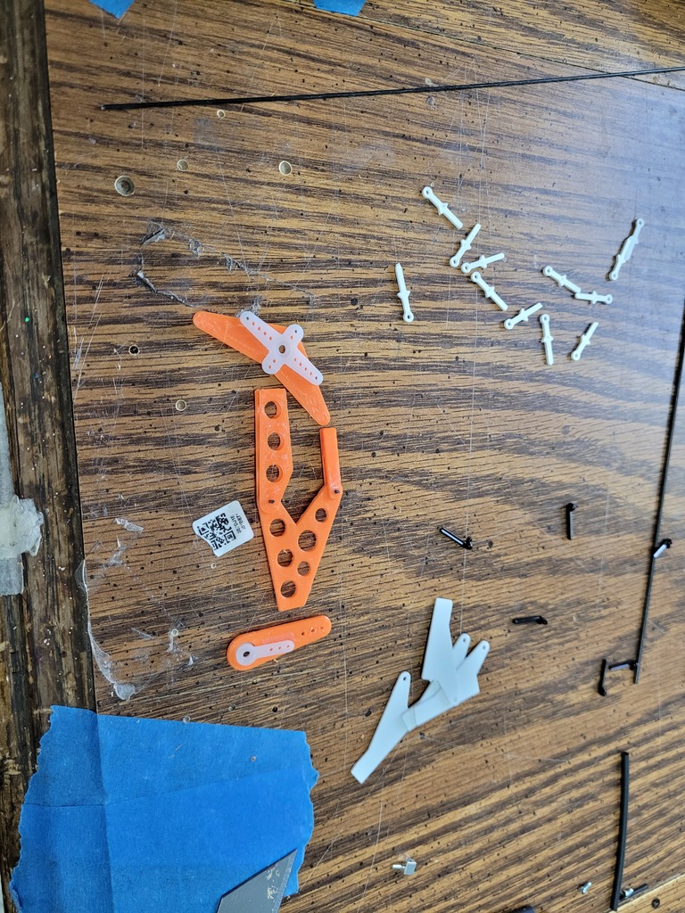
Hi, recently I built a Crack Laser and decided that I would experiment with 3D printing some better hardware. This equipment trades an extra approximately 5 grams to the build for zero slop linkages that reinforce the hinge at the control horn too. They also give you an exact 1:1 ratio between the control horn and servo horn which is generally ideal for good aerobatic throws while using the entirety of your radio system's extended limits. Using the full CRSF range of values, -120 to 120 % in opentx, which is PWM values 885us to 2115us, the 1:1 ratio is just nearly enough to hit the limit stops on the elevator of the Crack Laser. I included a slightly less than and slightly more than hole on the servo horns just in case you want a little more or less throw. Some might want more aileron for example like you would get from the stock hardware kit. On the rudder you may actually want to use the slightly less throw servo horn hole like I have because otherwise you hit the elevator before using the full CRSF range in the radio. A detailed assembly and install manual with pictures would be good. And I might bother to do this at some point in the future. But for now I'll just explain with words. Needed hardware and tools: Medium or Thin CA glue 1mm music wire or similar to use for pins 1mm or similar very tiny drill bit for cleaning up the holes after printing Needle nose pliers for holding things and pressing the pins through alligator clip for clamping the clevis to the pushrod can be helpful. ...................... Servo-horn Assembly: These are self explanatory, but if you are mindful during assembly you can eliminate any need for subtrim in your radio setup to allow you to get equal dynamic range from your radio system in both directions. Install your normal servo horns in the correct orientation for your model as centered as your can. Swap the included servo horns around between your servos till you find the most centered combination. Ensure you have NO trim and NO subtrim in your radio while doing this, so you are commanding the true center from your radio system. Dryfit the control horn extenders to the underside of the control horn. If you are using the Twisted CSP servos the servo horns in this set will be a snug fit on there. Reinstall the control horns. Now, with the radio system powered on and the stock servo horn as centered as it can be, rotate the horn extender to achieve the 90degree linkage geometry. You can measure or eyeball it's not completely critical but it's best to have it very close which you can do by eye. While holding this position, drill through the stock servo horn into the horn extender at the farthest hole. REMOVE the horn from the servo, cut a short length of the 1mm music wire, just a few mm, press through the hole you drilled, then lock it all together with CA. You REMOVED the horn from the servo before applying CA right? If you don't you risk getting CA in your servo and bruh I can't help you if you do that. Be very mindful not to get CA into the splines of the servo horn and ESPECIALLY mindful not get CA in your servo because that would really suck. I recommend you install the screw blocks now with the servo horns out of the plane because it will be much easier. My recommendation is the middle hole on the ailerons and elevator and the inner hole on the rudder. If you are using a radio system with a lower dynamic range than ELRS, you may want to use the outer holes. Spektrum for instance has slightly less dynamic range and you might not get enough throw with the above recommendation. I don't really recommend the inner holes on elevator and aileron unless you are specifically going for a tamer setup. The 1:1 ratio offered by the middle hole is plenty of precision, ............................ Hinge-horn Assembly: Combine the "hinge-horn" part and the "hinge-half" -Cut a short length of the music wire, about 5mm -Ream the holes at the top and bottom of the hinge horn and the end of the hinge halves -press the music wire through the hinge horn and hing halves, noting orientation. -apply a very very light dab of oil or grease into the hinge, the goal is to protect it from being CA'd too badly when we glue in the hinge horn The hinge-horn assembly is designed to attach a pushrod on the beveled side of the control surface. This is opposite what the included TH hardware kit is designed for on the tail surfaces. the pin should sit on the exact same plane as the live hinge. This will set the perfect depth for the front of the hinge horn. In the back, just line up the corners with the edge of the foam. If installing in thicker or thinner than 7.5mm foam which is about what the Crack Lite series uses, just use the corner of the part that is on the same side as the hinge pin. It's important to install the control horn correctly because this helps you get perfect geometry and equal throws in both directions. Installing the hinge horn: -Build your model to the point where you have it completely assembled minus the motor install, It's easiest to install these on an assembled models since they protrude through both sides of the foam. -Cut the normal TH control horn slot all the way through the foam. Be mindful to make this cut perpendicular to the surface of the foam. This is important -Cut another two slots into the other side of the hinge. Into the stab or wing depending on what control surface you are working on. When you cut this, you are essentially going for a "Y" shape but with the spread at the top of the "Y" being pretty tight. On my first few installs I tried to make these two slots parallel, but that needlessly increases the difficulty. Make a "Y" and aim for about 5-10mm apart at the top of the Y. This keeps the foam nice and beefy up in that zone and will make pushing the hinge halves into the foam easier -Take the assembled hinge horn and rotate the hinge halves back, as if the control surface was deflected 90 degrees toward the bevel. As in the hinge halves are covering the pin hole for the clevis. You essentially want to push the control horn into the control surface first. Insert all the way into the control surface and line up the hinge pin in the same plane as the stock live hinge as well as that back corner of the control horn with the same plane. -rotate the hinge-halves into their respective halves of the "Y" cut one at a time. You will need to fiddle with the foam inside the Y to make sure it's on the same plane as the rest of the stab or wing. -be mindful working with the assembled hinge horn and lining it up as perfectly as you can with the live hinge and control surface, it's important to install this correctly. -lock in place with CA, gentle mist with activator -repeat for all control surfaces Installing is a little more finicky than stock, but I hope anybody brave enough to try this will enjoy that it's actually easier to get proper geometry with this setup. Though if you don't you will likely have binding in your control surface which would be a bummer. ...................... Clevis Assembly: Assembling the clevises is the last thing you'll want to do and it's the easiest. -Drill out the pin holes in each half of each clevis. -Identify the clevises for the 1.5mm aileron pushrod and 1mm tail surface pushrods. -user pliers to clamp 2 halves together onto a pushrod with decent pressure and hold it there for a moment. You are trying to get a good firm fit between all these parts -Use helping hands or a free alligator clip to hold the halves of the clevis together onto the pushrod and lock in place with CA. If you need the ultimate strength for this assembly, use just a tiny tiny drop of it, enough to hold the part together, then wrap the joint with sewing thread and apply a couple decent drops to it -Line the clevis and pushrod up with the control and servo horns then cut the excess pushrod off -slide the screwblock end into the screw block and install the clevis onto the hinge horn by pressing a piece of the music wire through the clevis and through the hinge horn. This should be a tight fit and you shouldn't need glue or anything to keep it in place. But you can put a drop of CA here if needed. you will likely glue the clevis and hing horn together but if you cycle the joint a few times it should be fine. With all pushrods installed, power your radio system and line up your control surfaces and then lock the screwblocks down. ....................... Conclusion: Feel very pleased with yourself that you know you've just installed an over complicated linkage system on a foamie. But also that you know your servo horn to control horn ratio EXACTLY and that you have a system with no slop and play in it. The main motivator behind this idea was that normal EPP live hinges have flex and play in directions not related to to behing a hinge. They can stretch and compress and flex up and down and when any of this happens, the control surface deflects slightly or perhaps doesn't flex in the way the servo is commanding during a maneuver. In a high G push or pull, no doubt the load on the ailerons is compressing or stretching the hinge at the control horn and allowing the ailerons to give slightly during these moves. Maybe no big deal? Maybe not? But I do know this hinge horn system mostly eliminates the issue by instead of relying on a slivver of flexy epp not the stretch and compress, there is an actual hinge with a pin in it there that will not stretch or compress. The exact 1:1 servo/control horn ratio is just a bonus feature. This system is kind of a prototype and sized for the TH lite models which probably aren't goign to benefit much from it. But I plan on posting a scaled up version for the 39 inch models and probably the 43 inch models in the future as well.
With this file you will be able to print No-Slop linkage hardware for TH Crack Lite series airplanes with your 3D printer. Click on the button and save the file on your computer to work, edit or customize your design. You can also find more 3D designs for printers on No-Slop linkage hardware for TH Crack Lite series airplanes.