NovaPro V4 - Flex Shaft Driven Dual Feed Gear Extruder
prusaprinters
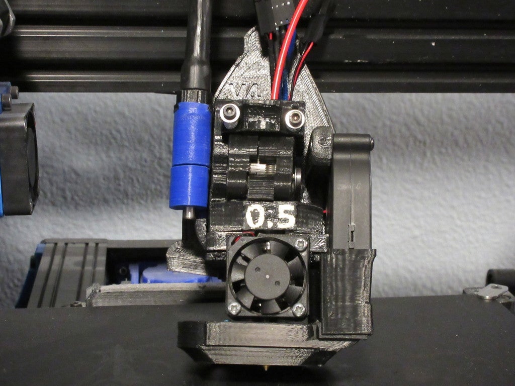
<p>Presenting the Nova Pro V4 Flex drive edition precision flexible shaft drive extruder! This project combines a flexible drive shaft locating the motor up on the frame, rather than on the moving carriage, with a bondtech drive gear set. The result is an extruder that while slightly larger than the Flex3drive or the Zesty nimble, has about twice the theoretical filament push force for around the same mass. It's also open source. I've included step files for most of the major components along with a complete bill of materials. If you need one of the other components in a different format, just let me know.</p> <p>The license on this is creative commons - Attribution - Non commercial. If anyone is interested in producing these, production licensing is available. I will likely also have a set of the main shafts made up for sale if there is enough interest.</p> <p>Commonly asked questions:</p> <ol> <li>How much flex is in the shaft, and does that affect precision?<br/> a: The flex shaft can flex approximately 1/4 turn in the direction of winding, slightly more against it. This however equates to around 1/16th of a gear tooth due to the 40:1 gear ratio, so I do not believe it will be a major concern. I am looking for a stiffer drive shaft option, perhaps one with a wrapping in both direction </li> <li>40:1 that's a high ratio, can you print at speed with that?<br/> a. currently I am still in testing, video footage will be uploaded soon, but from what I have seen so far I can print at my usual 130mm/sec speed just fine without any issues, though the motor does get a bit warmer than the greg/wade style I was running before. </li> <li>Whats the e-steps for this extruder?<br/> a. I'm still in testing, but it will end up being near 435. I'm still testing though. </li> <li>any plans for additional mounts?<br/> a. Yes, depending on the interest level. I've found it is difficult to make mounts to fit printers I don't actually have in front of me to take measurements from. </li> <li>Any plans for a dual extruder version?<br/> a. Yes! there is a dual extruder variant in the works using the heater block assembly from a Lulzbot Dual Extruder V3</li> <li><p>I see a NovaPro 1, and 2, what happened to version 3?<br/> a. Version 3 was the early prototype build of what became the Novapro V4 flex. The main differences were the mounting bolts for the extruder were rotated 90 degrees, which made mounting it somewhat problematic. I finally scrapped it and just redesigned the mount like I should have from the start, but technically this is a major revision hence it being Version 4.<br/> At any rate, I hope you enjoy the extruder, please feel free to ask me any questions or offer any feedback you might have. Thanks! Tim Pierce AKA Piercet.</p> <p>Bill of materials<br/> Flex shaft and motor:<br/> 1x 50mm section of 10.31mm/od 9mm id (13/32nd x .014 round brass or aluminum tube<br/> 1x Metal doorstop spring<br/> 2x M3 x 0.5mm heat set inserts <a href="https://www.mcmaster.com/94459a130">https://www.mcmaster.com/94459a130</a><br/> 6x M3 10mm hex head bolts<br/> 1x NEMA 17 motor (I used a Lulzbot supplied Moons Motor from the Taz 6)<br/> 1x 10 foot section of 6mm ID 8mm OD nylong tubing cut to length <a href="https://www.mcmaster.com/50405k36">https://www.mcmaster.com/50405k36</a><br/> 2x 12mm M5 bolts and 2x M5 drop in T nuts for mounting to extrusion.<br/> Approximately 6” heat shrink tubing that will fit over the 10.31mm tube<br/> Approximately 6” heavy wall heat shrink tubing (I sourced this locally) that will fit over the 13mm OD extruder end tube mount<br/> 1x foredom S-93 inner flex shaft (I sourced mine from this kit, you may be able to find the inner shaft by itself cheaper elsewhere https://www.amazon.com/gp/product/B00WTE6ZL8/ref=oh\_aui\_search\_detailpage?ie=UTF8&psc=1 )<br/> Assembly instructions:</p> </li> <li><p>Insert the 2 heat set inserts into Novapro_4_Flex_cable_anchor_housing_motor_side_2_1_c</p> </li> <li>Bolt your NEMA 17 motor to part Novapro_4_motor_mount_1_2_a with 4 M3 10mm bolts through the flex cable anchor housing. </li> <li>Insert the Novapro_4_flex_shaft_insert_1_0_a leaving a gap for the setscrew into the premade motor mount end of the fordom S-93 flex shaft, and install the shaft on the motor. </li> <li>Determine the length needed for your application. The entire length is required for a Taz. If you choose to shorten the cable you will need to find some sort of crimp end to fit on the cut off end. A small aluminum tube crimped in place can work here. If this is for a Taz, cut off approximately 14mm of the end shaft, and file down the notch until that piece fits inside the press fit drill bushing you will install on the extruder transmission cover later. </li> <li>Remove the door stop end from the door stop spring and cut off any excess that will not fit over the flexible shaft, then thread what remains through Novapro_4__motor_mount_spring_guide_hat_1_0_a </li> <li>Mount the spring hat and spring assembly to the flexible cable anchor. </li> <li>Slide the nylon tubing down the flexible shaft. You may wish to lubricate the flexible shaft for quieter operation. Cut the tubing where it will stop just short of where the metal end of the shaft begins. </li> <li>Slide the brass tube down until it covers the motor side end of the flexible shaft and the spring. Now slide a piece of heat shrink down until it overlaps the brass tube by 10mm at least, and shrink it down. </li> <li>Slide the heavy wall heat shrink tubing over the nylon shaft and then slide Novapro_4_Flex_cable_retainer_extruder_side_2_1_a into place on the end. Now shrink that heat shrink tubing until the nylon tube is secured to the retainer. </li> <li><p>Install a small piece of heat shrink tubing over the end of the flex shaft if a spacer is needed to center the end inside the worm gear that will be fitted later.<br/> Main extruder and mount assembly<br/> 1x Press fit drill bushing <a href="https://www.mcmaster.com/8486a426">https://www.mcmaster.com/8486a426</a><br/> 1x KHK Gears SW0.5-R1 worm gear, Module 0.5, Single Lead, Right Hand <a href="https://www.khkgears.us/catalog/product/SW0.5-R1">https://www.khkgears.us/catalog/product/SW0.5-R1</a><br/> 1x KHK Gears BG0.5-40R1, Module 0.5, 40 Tooth, Single Start, Right Hand <a href="https://www.khkgears.us/catalog/product/BG0.5-40R1">https://www.khkgears.us/catalog/product/BG0.5-40R1</a> (some project photos show the Nylon variant, that proved unsuitable for long term use)<br/> 2x 10mm long-ish bed mount springs (or idler latch springs)<br/> 4x M3 washers<br/> 1x 5v 30mm fan (or whatever voltage your board uses for the cooling fan)<br/> 1x 24v 52mm Radial blower fan (I used this one) <a href="https://itworks3d.com/product/blower-fan-52mm-24v/">https://itworks3d.com/product/blower-fan-52mm-24v/</a><br/> 17x M3 x 0.5mm heat set inserts <a href="https://www.mcmaster.com/94459a130">https://www.mcmaster.com/94459a130</a><br/> 1x E3Dv6 Hot end assembly for 3.0mm filament <a href="https://e3d-online.com/catalogsearch/result/?q=v6">https://e3d-online.com/catalogsearch/result/?q=v6</a><br/> 1x set of Bondtech drive gears for 3.0mm filament / 8mm shaft and assorted shaft, bearings etc. <a href="https://www.bondtech.se/en/product/drivegear-kits/">https://www.bondtech.se/en/product/drivegear-kits/</a><br/> 1x 128-27 bearing for 8MM shaft <a href="https://www.mcmaster.com/7804k115">https://www.mcmaster.com/7804k115</a><br/> 1x 688-2z bearing for 8mm shaft <a href="https://www.mcmaster.com/7804k117">https://www.mcmaster.com/7804k117</a><br/> 1x custom 8mm to 5mm bolt thingy<br/> 1x 20mm section of 5mm steel shaft,<br/> 2 part epoxy<br/> 5x M3 nuts (2 of them need to be standard nuts, and 4 this application I would recommend against nylocs for the other 3.<br/> 1x Round E3dv6 compact mount (similar to this one: <a href="https://www.ebay.com/itm/Hotend-Aluminum-Mount-For-Delta-RepRap-Rostock-Kossel-Mini-3D-Printer-V5-V6-UE/332393586277">https://www.ebay.com/itm/Hotend-Aluminum-Mount-For-Delta-RepRap-Rostock-Kossel-Mini-3D-Printer-V5-V6-UE/332393586277</a><br/> 4x 20mm M3 cap head bolts<br/> 2x 22mm M3 cap head bolts<br/> 4x 14mm M3 bolts<br/> 8x m3 8mm bolts<br/> 1x 26mm M3 cap head bolt<br/> 2x 16mmM3 cap head bolts<br/> 2x small 5mm ID bearings (I think these are 85-2Z, but I’m not certain.) <a href="https://www.mcmaster.com/7804k104">https://www.mcmaster.com/7804k104</a><br/> 2x small zip ties.<br/> Small amount of paint for the lettering of the inserts, if desired.<br/> Assorted wires, connector ends and crimp fittings to finish your wire harness<br/> Extruder assembly:</p> </li> <li><p>Remove any support and clean the main extruder body, then Insert the 7 M3 heat set inserts into the designated locations on the main extruder body, and the 3 additional ones into the main mount, plus 2 more into the idler half. Heat sets into the blower duct and lower blower cooling duct may be also installed at this time.</p> </li> <li>Insert the 128-27 bearing into the front of the extruder body, then insert the 8mm to 5mm bolt. I put a small washer in between the bolt head and the bearing, but this is likely optional </li> <li>Slide the main bondtech drive gear down onto the bolt and line up with the inner filament track. Secure it using the setscrew to the flat spot on the bolt.</li> <li>Now install the 688-2z bearing in the back. You may install the brass KHK gear as well at this time on the 5mm section of the shaft. </li> <li>Place an ID tag into the side of the extruder under the idler latch (or the blank tag if no lable is desired) and then set the extruder in place on the main mount, making sure not to pinch any wires. You may want to loosely preinstall the lower zip tie at this point. </li> <li>Now insert the 3 M3 nuts into the top deck of the extruder lower section, and carefully fit the E3dv6 extruder barrel assembly and round mount up into the bottom of the cold end. For cleaner installation pre-insert the 4 14mm M3 bolts through the main mount holes. There may be some miner burring of the E3Dv6 barrel otherwise. You can alternatively use minimal clearance M3 bolt heads here if you can source or make them. </li> <li>Now build the idler by installing the other bondtech gear and its shaft in between Novapro_4_Half_1_RH_2_0_a and Novapro_4_Idler_Half_2_RH_2_0_a, then use M3 bolts to secure them together. Ensure the idler gear turns freely and that the direction of the bondtech gear lines up with the sprocket teeth towards the rear of the idler. See pictures for orientation. </li> <li>Install the idler assembly with a 20mm long M3 bolt. </li> <li>Now drop the remaining 2 M3 nuts into the two top rectangular holes in the extruder body. Make sure you already cleaned out all of the support material inside this area. Fit whichever version of the idler latch appeals to you over the idler, then insert 2 M3 washers into the recess holes, then install the spring, another washer and a 22mm long M3 bolt to complete the M3 tensioner, one on either side. Ensure the idler latch assembly can move up and down in the long slot smoothly. If it binds here, use a flat head screwdriver to remove the remaining internal support as needed.</li> <li>Install 2 M3 heat set inserts into Novapro_4_blower_duct_and_30mm_fan_mount_2_0_a and then install the 5v 30mm fan with the cables towards the top and the fan set with the back supports towards the E3Dv6 so that air is passing over it (see pictures). Route the power cables up the back of the extruder using the provided path. </li> <li>Set Novapro_4_Lower_back_duct_3_1_b in place and route the main hotend power and thermistor wires up via the cable passthrough (see pictures). Secure the entire assembly using 2x 20mm M3 bolts to the bottom of the extruder cold end</li> <li>With the idler latch open, insert the 26mm bolt through the uepr extruder cold end and into the back mount. </li> <li>Now mount the blower fan using two 20mm cap head bolts. Route the wires up the back path with the others as seen in the pictures</li> <li>Bolt Novapro_4_Blower_fan_duct_intake_extension_2_1_a to the main fan mount using 2x M3 8mm bolts. Now ensure the E3dV6 is rotated properly for clearance (see pictures) and bolt on the Novapro_4_Lower_blower_cooling_duct_4_1_c with 2 more M# 8mm bolts. </li> <li>Take the worm gear and the 5mm shaft, and epoxy the shaft inside the worm gear making sure to install it in the lower half of the worm (specifically not the part with the setscrew) it is critical that this shaft be aligned parallel with the worm gear and that the setscrew can still be used to attach the flexible shaft in the next step. Wait for the epoxy to dry and cure before proceeding. </li> <li>Next, fit the drill bushing up into Novapro_4_top_gear_housing_1_0_a and slide that assembly up onto the flex shaft assembly where it meets Novapro_4_Flex_cable_retainer_extruder_side_2_1_a, Secure the worm gear assembly to the shaft using the setscrew</li> <li>Slide a 85-2Z bearing over the 5mm section of the main shaft protruding from the back of the brass gear, then fit the top gear housing assembly over that gear so the worm is engaging the main gear. </li> <li>Install a second 85-2Z into the Novapro_4_tbottom_gear_housing_1_0_a and secure both housings to the main extruder body using 8mm M3 bolts. You may wish to install some gear lubricant to reduce noise at that time. </li> <li>Tighten the zip ties so they are flush to the back of the mount, finish any elecrtrical work, test your filament path, then you should be ready to install!<br/> Notes: The Taz stock firmware motor direction is reversed from what this extruder needs. You may either alter the firmware, or change one of the coil pairs on the motor to reverse it. The Esteps should theoretically be something like 435, but further testing is required at this point.</li> </ol> <h3>Print instructions</h3><p>Unassociated tags: flexible shaft</p> <h3>Category: 3D Printer Extruders Summary</h3> <p>Presenting the Nova Pro V4 Flex drive edition precision flexible shaft drive extruder! This project combines a flexible drive shaft locating the motor up on the frame, rather than on the moving carriage, with a bondtech drive gear set. The result is an extruder that while slightly larger than the Flex3drive or the Zesty nimble, has about twice the theoretical filament push force for around the same mass. It's also open source. I've included step files for most of the major components along with a complete bill of materials. If you need one of the other components in a different format, just let me know.</p> <p>The license on this is creative commons - Attribution - Non commercial. If anyone is interested in producing these, production licensing is available. I will likely also have a set of the main shafts made up for sale if there is enough interest.</p> <p>Commonly asked questions:</p> <ol> <li>How much flex is in the shaft, and does that affect precision?<br/> a: The flex shaft can flex approximately 1/4 turn in the direction of winding, slightly more against it. This however equates to around 1/16th of a gear tooth due to the 40:1 gear ratio, so I do not believe it will be a major concern. I am looking for a stiffer drive shaft option, perhaps one with a wrapping in both direction </li> <li>40:1 that's a high ratio, can you print at speed with that?<br/> a. currently I am still in testing, video footage will be uploaded soon, but from what I have seen so far I can print at my usual 130mm/sec speed just fine without any issues, though the motor does get a bit warmer than the greg/wade style I was running before. </li> <li>Whats the e-steps for this extruder?<br/> a. I'm still in testing, but it will end up being near 435. I'm still testing though. </li> <li>any plans for additional mounts?<br/> a. Yes, depending on the interest level. I've found it is difficult to make mounts to fit printers I don't actually have in front of me to take measurements from. </li> <li>Any plans for a dual extruder version?<br/> a. Yes! there is a dual extruder variant in the works using the heater block assembly from a Lulzbot Dual Extruder V3</li> <li><p>I see a NovaPro 1, and 2, what happened to version 3?<br/> a. Version 3 was the early prototype build of what became the Novapro V4 flex. The main differences were the mounting bolts for the extruder were rotated 90 degrees, which made mounting it somewhat problematic. I finally scrapped it and just redesigned the mount like I should have from the start, but technically this is a major revision hence it being Version 4.<br/> At any rate, I hope you enjoy the extruder, please feel free to ask me any questions or offer any feedback you might have. Thanks! Tim Pierce AKA Piercet.</p> <p>Bill of materials<br/> Flex shaft and motor:<br/> 1x 50mm section of 10.31mm/od 9mm id (13/32nd x .014 round brass or aluminum tube<br/> 1x Metal doorstop spring<br/> 2x M3 x 0.5mm heat set inserts <a href="https://www.mcmaster.com/94459a130">https://www.mcmaster.com/94459a130</a><br/> 6x M3 10mm hex head bolts<br/> 1x NEMA 17 motor (I used a Lulzbot supplied Moons Motor from the Taz 6)<br/> 1x 10 foot section of 6mm ID 8mm OD nylong tubing cut to length <a href="https://www.mcmaster.com/50405k36">https://www.mcmaster.com/50405k36</a><br/> 2x 12mm M5 bolts and 2x M5 drop in T nuts for mounting to extrusion.<br/> Approximately 6” heat shrink tubing that will fit over the 10.31mm tube<br/> Approximately 6” heavy wall heat shrink tubing (I sourced this locally) that will fit over the 13mm OD extruder end tube mount<br/> 1x foredom S-93 inner flex shaft (I sourced mine from this kit, you may be able to find the inner shaft by itself cheaper elsewhere https://www.amazon.com/gp/product/B00WTE6ZL8/ref=oh\_aui\_search\_detailpage?ie=UTF8&psc=1 )<br/> Assembly instructions:</p> </li> <li><p>Insert the 2 heat set inserts into Novapro_4_Flex_cable_anchor_housing_motor_side_2_1_c</p> </li> <li>Bolt your NEMA 17 motor to part Novapro_4_motor_mount_1_2_a with 4 M3 10mm bolts through the flex cable anchor housing. </li> <li>Insert the Novapro_4_flex_shaft_insert_1_0_a leaving a gap for the setscrew into the premade motor mount end of the fordom S-93 flex shaft, and install the shaft on the motor. </li> <li>Determine the length needed for your application. The entire length is required for a Taz. If you choose to shorten the cable you will need to find some sort of crimp end to fit on the cut off end. A small aluminum tube crimped in place can work here. If this is for a Taz, cut off approximately 14mm of the end shaft, and file down the notch until that piece fits inside the press fit drill bushing you will install on the extruder transmission cover later. </li> <li>Remove the door stop end from the door stop spring and cut off any excess that will not fit over the flexible shaft, then thread what remains through Novapro_4__motor_mount_spring_guide_hat_1_0_a </li> <li>Mount the spring hat and spring assembly to the flexible cable anchor. </li> <li>Slide the nylon tubing down the flexible shaft. You may wish to lubricate the flexible shaft for quieter operation. Cut the tubing where it will stop just short of where the metal end of the shaft begins. </li> <li>Slide the brass tube down until it covers the motor side end of the flexible shaft and the spring. Now slide a piece of heat shrink down until it overlaps the brass tube by 10mm at least, and shrink it down. </li> <li>Slide the heavy wall heat shrink tubing over the nylon shaft and then slide Novapro_4_Flex_cable_retainer_extruder_side_2_1_a into place on the end. Now shrink that heat shrink tubing until the nylon tube is secured to the retainer. </li> <li><p>Install a small piece of heat shrink tubing over the end of the flex shaft if a spacer is needed to center the end inside the worm gear that will be fitted later.<br/> Main extruder and mount assembly<br/> 1x Press fit drill bushing <a href="https://www.mcmaster.com/8486a426">https://www.mcmaster.com/8486a426</a><br/> 1x KHK Gears SW0.5-R1 worm gear, Module 0.5, Single Lead, Right Hand <a href="https://www.khkgears.us/catalog/product/SW0.5-R1">https://www.khkgears.us/catalog/product/SW0.5-R1</a><br/> 1x KHK Gears BG0.5-40R1, Module 0.5, 40 Tooth, Single Start, Right Hand <a href="https://www.khkgears.us/catalog/product/BG0.5-40R1">https://www.khkgears.us/catalog/product/BG0.5-40R1</a> (some project photos show the Nylon variant, that proved unsuitable for long term use)<br/> 2x 10mm long-ish bed mount springs (or idler latch springs)<br/> 4x M3 washers<br/> 1x 5v 30mm fan (or whatever voltage your board uses for the cooling fan)<br/> 1x 24v 52mm Radial blower fan (I used this one) <a href="https://itworks3d.com/product/blower-fan-52mm-24v/">https://itworks3d.com/product/blower-fan-52mm-24v/</a><br/> 17x M3 x 0.5mm heat set inserts <a href="https://www.mcmaster.com/94459a130">https://www.mcmaster.com/94459a130</a><br/> 1x E3Dv6 Hot end assembly for 3.0mm filament <a href="https://e3d-online.com/catalogsearch/result/?q=v6">https://e3d-online.com/catalogsearch/result/?q=v6</a><br/> 1x set of Bondtech drive gears for 3.0mm filament / 8mm shaft and assorted shaft, bearings etc. <a href="https://www.bondtech.se/en/product/drivegear-kits/">https://www.bondtech.se/en/product/drivegear-kits/</a><br/> 1x 128-27 bearing for 8MM shaft <a href="https://www.mcmaster.com/7804k115">https://www.mcmaster.com/7804k115</a><br/> 1x 688-2z bearing for 8mm shaft <a href="https://www.mcmaster.com/7804k117">https://www.mcmaster.com/7804k117</a><br/> 1x custom 8mm to 5mm bolt thingy<br/> 1x 20mm section of 5mm steel shaft,<br/> 2 part epoxy<br/> 5x M3 nuts (2 of them need to be standard nuts, and 4 this application I would recommend against nylocs for the other 3.<br/> 1x Round E3dv6 compact mount (similar to this one: <a href="https://www.ebay.com/itm/Hotend-Aluminum-Mount-For-Delta-RepRap-Rostock-Kossel-Mini-3D-Printer-V5-V6-UE/332393586277">https://www.ebay.com/itm/Hotend-Aluminum-Mount-For-Delta-RepRap-Rostock-Kossel-Mini-3D-Printer-V5-V6-UE/332393586277</a><br/> 4x 20mm M3 cap head bolts<br/> 2x 22mm M3 cap head bolts<br/> 4x 14mm M3 bolts<br/> 8x m3 8mm bolts<br/> 1x 26mm M3 cap head bolt<br/> 2x 16mmM3 cap head bolts<br/> 2x small 5mm ID bearings (I think these are 85-2Z, but I’m not certain.) <a href="https://www.mcmaster.com/7804k104">https://www.mcmaster.com/7804k104</a><br/> 2x small zip ties.<br/> Small amount of paint for the lettering of the inserts, if desired.<br/> Assorted wires, connector ends and crimp fittings to finish your wire harness<br/> Extruder assembly:</p> </li> <li><p>Remove any support and clean the main extruder body, then Insert the 7 M3 heat set inserts into the designated locations on the main extruder body, and the 3 additional ones into the main mount, plus 2 more into the idler half. Heat sets into the blower duct and lower blower cooling duct may be also installed at this time.</p> </li> <li>Insert the 128-27 bearing into the front of the extruder body, then insert the 8mm to 5mm bolt. I put a small washer in between the bolt head and the bearing, but this is likely optional </li> <li>Slide the main bondtech drive gear down onto the bolt and line up with the inner filament track. Secure it using the setscrew to the flat spot on the bolt.</li> <li>Now install the 688-2z bearing in the back. You may install the brass KHK gear as well at this time on the 5mm section of the shaft. </li> <li>Place an ID tag into the side of the extruder under the idler latch (or the blank tag if no lable is desired) and then set the extruder in place on the main mount, making sure not to pinch any wires. You may want to loosely preinstall the lower zip tie at this point. </li> <li>Now insert the 3 M3 nuts into the top deck of the extruder lower section, and carefully fit the E3dv6 extruder barrel assembly and round mount up into the bottom of the cold end. For cleaner installation pre-insert the 4 14mm M3 bolts through the main mount holes. There may be some miner burring of the E3Dv6 barrel otherwise. You can alternatively use minimal clearance M3 bolt heads here if you can source or make them. </li> <li>Now build the idler by installing the other bondtech gear and its shaft in between Novapro_4_Half_1_RH_2_0_a and Novapro_4_Idler_Half_2_RH_2_0_a, then use M3 bolts to secure them together. Ensure the idler gear turns freely and that the direction of the bondtech gear lines up with the sprocket teeth towards the rear of the idler. See pictures for orientation. </li> <li>Install the idler assembly with a 20mm long M3 bolt. </li> <li>Now drop the remaining 2 M3 nuts into the two top rectangular holes in the extruder body. Make sure you already cleaned out all of the support material inside this area. Fit whichever version of the idler latch appeals to you over the idler, then insert 2 M3 washers into the recess holes, then install the spring, another washer and a 22mm long M3 bolt to complete the M3 tensioner, one on either side. Ensure the idler latch assembly can move up and down in the long slot smoothly. If it binds here, use a flat head screwdriver to remove the remaining internal support as needed.</li> <li>Install 2 M3 heat set inserts into Novapro_4_blower_duct_and_30mm_fan_mount_2_0_a and then install the 5v 30mm fan with the cables towards the top and the fan set with the back supports towards the E3Dv6 so that air is passing over it (see pictures). Route the power cables up the back of the extruder using the provided path. </li> <li>Set Novapro_4_Lower_back_duct_3_1_b in place and route the main hotend power and thermistor wires up via the cable passthrough (see pictures). Secure the entire assembly using 2x 20mm M3 bolts to the bottom of the extruder cold end</li> <li>With the idler latch open, insert the 26mm bolt through the uepr extruder cold end and into the back mount. </li> <li>Now mount the blower fan using two 20mm cap head bolts. Route the wires up the back path with the others as seen in the pictures</li> <li>Bolt Novapro_4_Blower_fan_duct_intake_extension_2_1_a to the main fan mount using 2x M3 8mm bolts. Now ensure the E3dV6 is rotated properly for clearance (see pictures) and bolt on the Novapro_4_Lower_blower_cooling_duct_4_1_c with 2 more M# 8mm bolts. </li> <li>Take the worm gear and the 5mm shaft, and epoxy the shaft inside the worm gear making sure to install it in the lower half of the worm (specifically not the part with the setscrew) it is critical that this shaft be aligned parallel with the worm gear and that the setscrew can still be used to attach the flexible shaft in the next step. Wait for the epoxy to dry and cure before proceeding. </li> <li>Next, fit the drill bushing up into Novapro_4_top_gear_housing_1_0_a and slide that assembly up onto the flex shaft assembly where it meets Novapro_4_Flex_cable_retainer_extruder_side_2_1_a, Secure the worm gear assembly to the shaft using the setscrew</li> <li>Slide a 85-2Z bearing over the 5mm section of the main shaft protruding from the back of the brass gear, then fit the top gear housing assembly over that gear so the worm is engaging the main gear. </li> <li>Install a second 85-2Z into the Novapro_4_tbottom_gear_housing_1_0_a and secure both housings to the main extruder body using 8mm M3 bolts. You may wish to install some gear lubricant to reduce noise at that time. </li> <li>Tighten the zip ties so they are flush to the back of the mount, finish any elecrtrical work, test your filament path, then you should be ready to install!<br/> Notes: The Taz stock firmware motor direction is reversed from what this extruder needs. You may either alter the firmware, or change one of the coil pairs on the motor to reverse it. The Esteps should theoretically be something like 435, but further testing is required at this point. <h3>Print Settings</h3> </li> </ol> <p><strong>Printer Brand:</strong> LulzBot</p> <p><strong>Printer:</strong> Mini 2</p> <p><strong>Rafts:</strong> No</p> <p><strong>Supports:</strong> Yes</p> <p><strong>Resolution:</strong> 0.5mm nozzle</p> <p><strong>Infill:</strong> 85% or better</p> <p><strong>Filament:</strong> Push Plastic ABS Black and Blue<br/> <strong>Notes:</strong></p> <p>Some parts will need support, especially the duct components. The main body has its required support built in.</p> <p>also, the make and model section is screwed up. It's printed on a Taz 5-ish heavily modified printer.</p>
With this file you will be able to print NovaPro V4 - Flex Shaft Driven Dual Feed Gear Extruder with your 3D printer. Click on the button and save the file on your computer to work, edit or customize your design. You can also find more 3D designs for printers on NovaPro V4 - Flex Shaft Driven Dual Feed Gear Extruder.