Octoshield Case for Raspberry Pi 4 for Prusa Mk3
prusaprinters
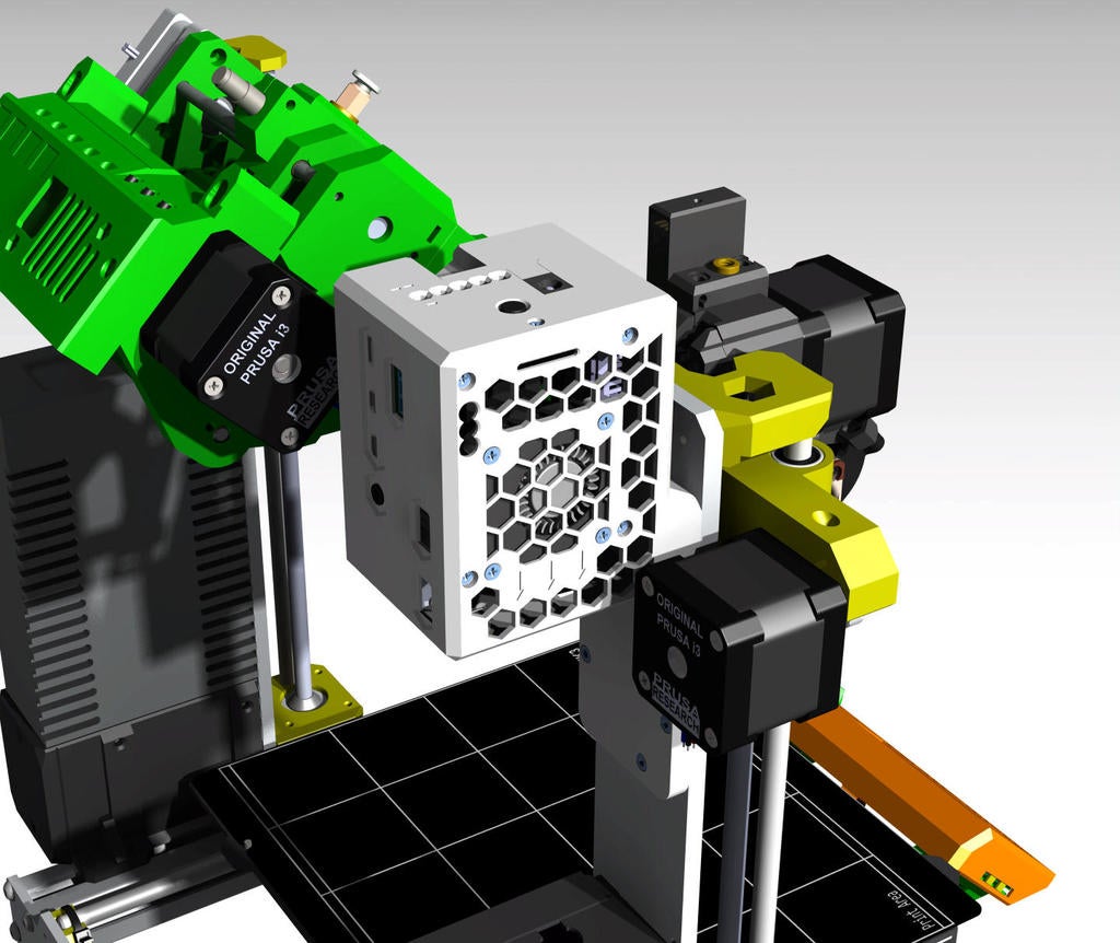
<p>I am using Octoprint (<a href="https://octoprint.org/">https://octoprint.org/</a>) to manage my 3d printer and I bumped into a really nice plugin called “OctoPrint-Enclosure” (<a href="https://plugins.octoprint.org/plugins/enclosure/">https://plugins.octoprint.org/plugins/enclosure/</a>).<br/>I found the functionality brought by this plugin useful as I am myself using and Enclosure for my printer.</p><p>The very same person who wrote this plugin, vitormhenrique, posted a thing (<a href="https://www.thingiverse.com/thing:2245493">https://www.thingiverse.com/thing:2245493</a>) where he was sharing his hardware set up.<br/>At this point I got really scared by the amount of cable swarming everywhere as I am myself trying to keep my “working place” as neat as possible.</p><p>So, I started to look around trying to find an all-integrated solution for my enclosure. This is where I found the nice project on hackaday called “Octoshield” (<a href="https://hackaday.io/project/172223-octoshield">https://hackaday.io/project/172223-octoshield</a>). It is basically a HAT rerouting Raspberry Pi’s GPIO and having all electronics component already assembled (handy). So, you simply need to connect your sensor, your switch, LEDs and other fans to your Raspberry Pi and install the plugin for having everything operational (cool).</p><p>Only problem is that you need to build it yourself and because I am not found of soldering tiny things I decided to “subcontract” the production of the HAT to the company mentioned in the Youtube video link of the Hackaday project. This project has been realized by goodwin for which I must give all credit to (good job).</p><p>In a nutshell the “Octoshield” HAT allows you to :</p><ul><li>Plug a temperature sensor</li><li>Plug a 5V fan to cool the Raspberry Pi</li><li>Plug a 12V fan for your enclosure</li><li>Add an input (switch or sensor)</li><li>Plug RGB LED stripes</li><li>Plug Neopixel LED stripes</li><li>Control a relay</li></ul><p>Power the raspberry pi with a 12V power input instead of the 5V USB C. To keep things shorts, you must purchase the Printed Circuit Board (or PCB) which is cheap to be honest (You get 5 pieces for 40$ I think). Then you have the possibility either to weld all components by yourself, meaning that you must source all parts yourself, or you have the possibility to ask the PCB company to do it for you (yes!). They will source the components and have them mounted for you. This will cost you an extra 40$. Otherwise, I think you can get all component for 10$.</p><p>I am attaching the component list for the HAT, other relevant information to have the HAT built and the details of the purchasing basket I used. The team is friendly, and they will help you build it easily. I must admit my interest in electronic does not go that deep, but you do not really need to know a lot to order the PCB fully assembled.</p><p>Once I received my “Octoshields” (I order more than one fully assembled) and after making the different test to have all component working with “OctoPrint-Enclosure” plugin I started designing the case for the Raspberry Pi + Octoshield + All component. As mentioned, before I wanted to have enclosure function all included in a box so to have something compact and neat (bad cables, bad).</p><p>For this project, my requirements were as follow (following Octoshield capacities):</p><p>Have a temperature + humidity sensor to monitor my enclosure environment.</p><ul><li>Be able to control the printer’s PSU trough a relay (On/Off)).</li><li>Control the air management in the enclosure (Fans).</li><li>Cool down the Raspberry Pi4 (Must be done it is over heating).</li><li>Have a Raspberry Pi Cam plugged.</li><li>Have a Webcam plugged.</li><li>Have a DSI screen plugged.</li><li>Power the Raspberry Pi.</li></ul><p>Mount it to my printer’s frame. I designed a case as compact as possible to be able to fit all component and have opening for every cables.</p><p>Mounting instruction are given here below</p><h3>Print Settings</h3><p><strong>Rafts:</strong></p><p>No</p><p><strong>Supports:</strong></p><p>No</p><p><strong>Resolution:</strong></p><p>0.2</p><p><strong>Infill:</strong></p><p>20</p><p><strong>Filament:</strong> Any PETG or PLA <br/><strong>Notes:</strong></p><p><strong>Mounting instruction:</strong></p><ol><li>Break away the supports from Case B for the inner fan channel and the openings.</li><li>Mount the 5V axial fan (3) with the help of 4 M4 M5 (18) screws on the Case A, pay attention to the orientation of the cable to have enough length.</li><li>Mount the wired DHT22 (AM2302) (6) with the help of 2 M2 10mm (9) screws and 2 M2 nuts (10) (M2.5 works too).</li><li>Mount the DHT22 Cover with 2 M2.5 10mm screws. The cover’s function is to “isolate” the sensor from the Raspberry pi in order t avoid having the board radiating heat on the sensor. You can tap it with Aluminum tape if you want to make things even more performing or use white filament type.</li><li>Heatsinks:<br/>a. Put the Heatsinks (8) as show on the picture, to avoid any collision with the Bulk module mounted on the Octoshield HAT, offset the heatsink as shown. I am using two 14x10x6 mm heatsink. Make some trial to be sure to avoid collision.<br/>b. Do the same for the Octoshield ‘s Bulk module. Once the HAT is mounted all heatsinks must be side to side and not facing each other. I am using one 9x9x5 mm heatsink for the Octoshield.</li><li>Mount the Raspberry Pi board (1) in the Case A by using 4 M2.5 10mm screws (11) and 4 M2.5 11mm Hexagonal spacers (12).</li><li>If you are using the Raspberry Pi can and or a DSI screen, connect the Ribbon cables (22 and 23). For the sake of cable management later, I would suggest not to use the Camera’s ribbon slit and pass the camera ribbon under the Octoshield HAT.</li><li>You can know mount the Octoshield HAT (X) on the Raspberry Pi (1).</li><li>Connect the DHT22’s (6) 3-wires cable to J6. Mind the order. The ground pin is the one closest to the camera ribbon slit.</li><li>Connect the 3Pin Y cable (1) to J9 and to the radial fan’s cable (3). Pay attention to the DSI ribbon cable.</li><li>Add the M2.5 20mm hexagonal spacer (14) on top of the Raspberry Pi 4.</li><li>Wire the 12x12x6mm tactile button (24) and prepare to mount it to the Case B:<br/>a. Screw first the M2.5 4mm screw (15) in Case C<br/>b. Then mount the button against Case B and block it in position with Case C.<br/>c. Fix Case C with M2.5 6mm screw (16).<br/>d. For the cable you can use Dupont connectors (7). A 3 pins connector can be use on button side as the spacing between Pins 1 and 3 matches exactly the button legs. For the other side, a 2 pins head is needed.<br/>e. The length of the cable should be more or less the same as the case’s length.<br/>Note : Using Dupont connector is a good way not to weld the cable to the switch.</li><li>Mount the Centrifugal Fan (5) with the help of 4 screws M2.5 12mm (13). Take care to put the outlet facing the channel inlet. (and make sure you removed the supports…).</li><li>Wiring (take care of cable management everything fits but you must do it neatly):<br/>a. Connect the centrifugal power cable to the 3Pin Y cable (1) used previously. There is 2 fans power by a 5V output to cool the boards.<br/>b. Connect the button + cable (24+4) to J8.<br/>c. Connect the 12v fan cable through the case B opening facing J4. You may use a short cable extender or Y cable for ease of use.<br/>d. If you want to connect any LEDs you can do it trough J5 and J3 interfaces. I am not using them for the moment.</li></ol><p>At this stage before closing the case I advise you to try to power the Raspberry Pi and make your verification. Check with Octoprint if all equipment are running and that you can communicate normally with them. Check also if both 5V fans are running. For the button, an easy way to see if it is working is to program it to turn on and off the Relay in the plugin interface. If all your wiring is nicely done you can :<br/>a. Close the Case A against Case B, pay attention not to pinch any cable. Screw the assembly together with the last four M2.5 12mm screws (13).<br/>b. You can connect your power cable to the relay through the terminal block. I use the NC (Normally Closed = Circuit is powered) and COM ports (left and middle). This way my printer turns on when I power my Raspberry Pi. If I am not wrong, you should use the red or brown cable of the power cord. Note : Fan channel will fit between the Octoshield HAT and the Raspberry Pi, and the fan will be able to blow air in the space between the 2 boards.<br/>Attention : Before using the Octoshield HAT with the Raspberry Pi make sure that the bulk module is properly set and delivers as output more or less 5.15V. You can do this by powering the HAT and checking with a multimeter the tension between the pads show here below. Make sure you do this otherwise you may destroy your Raspberry Pi board.</p><p>You are done! Or are you ?</p><p>You can now mount the assembled case using four M3 10 mm (17) screws onto you Prusa MK3S frame above the Einsy board.</p><ol><li>Connect your DSI screen if any.</li><li>Connect your Raspberry Pi camera if any.</li><li>Connect any USB device if needed (webcam).</li><li>Connect the enclosure fan if you use a cable extender as I do.</li><li>Connect the Raspberry Pi to the Einsy board with the short USB cable (25).</li><li>Power the Raspberry Pi with the 12V power supply (20). And now you are done ! For the hardware part…</li></ol><p>Category: 3D Printer Accessories</p>
With this file you will be able to print Octoshield Case for Raspberry Pi 4 for Prusa Mk3 with your 3D printer. Click on the button and save the file on your computer to work, edit or customize your design. You can also find more 3D designs for printers on Octoshield Case for Raspberry Pi 4 for Prusa Mk3.