Odroid H2+ Case
thingiverse
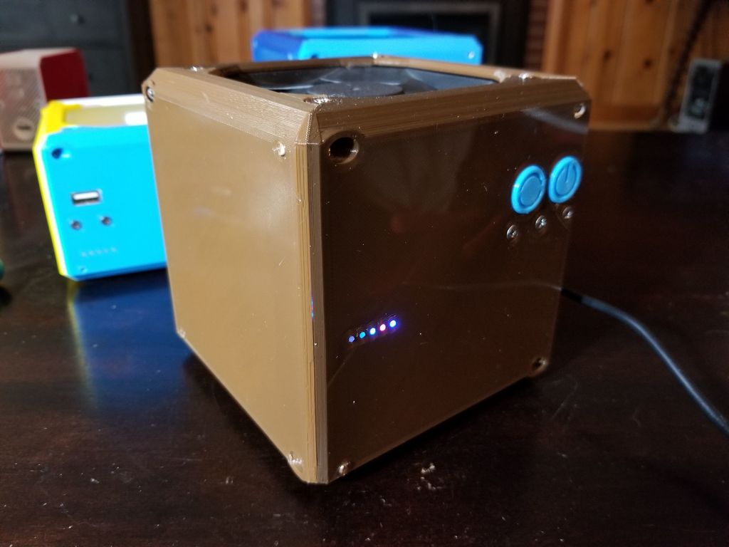
This is a case I made for the Odroid H2+ "single board" computer. If you don't know what that is, it's an tiny (110mm x 100mm) X86 computer with a J4115 Intel Celeron processor. The specs don't look like much on paper, but it's surprisingly capable. I put "single board" in quotes because it's not really a traditional single board computer. It requires you to install your own SODIMM RAM. It has an M.2 NVME 2280 connector and two SATA connectors. It's really more like a little tiny motherboard than a single board computer. I personally find it is great for streaming 4K videos and web browsing, although I also did the CAD work for much of this case on the board itself, so it can do some relatively heavy listing for such a small, low cost computer. It's also pretty useful as a NAS since it has actual SATA connectors and a fast ethernet connection. Even just as a Samba shared folder in Windows works great. There are two versions of this case that I made. One is a 118mm cube. The other is 118x118x80mm. 118 cube has room in the basement for a 2.5" SSD. This will require a 90 degree SATA adapter. https://www.amazon.com/dp/B00S5WPSZ2/ref=cm_sw_su_dp The case is designed to work with the Odroid 92mm accessory fan. Other 92mm fans will probably work but the Odroid fan is quite and has the correct connector and an acceptable length of wire. The board has physical power and reset buttons on the edge opposite the ports. I have made rocker arm buttons that activate these buttons on the board. They attach to the inside of the case with the part named PILLOW. There are holes in the printed rocker arm buttons for pieces of 1.75mm filament to act as springs. This is my first attempt at such a contraption and I feel it worked out surprisingly well. There are holes in the case near the LEDs on the board. These holes are designed at 1.8mm. They are intended to take short pieces of translucent 1.75mm filament so act as fiberoptic elements. It works really well - see pics. You may need to clean the holes out with a small drill bit to get the filament to fit. I use a drill bit that measures 1.6mm with my calipers and it makes holes that are a perfect fit for 1.75mm filament. I personally use clear PETG. You might be able to put a second drive in the basement with the right set of 90 degree adapters. So I put a second set of screw holes on the brackets. There's also various sides with grills or no grills. The portsSIDEyesGRILLS part, the grill is below the board, which you would think would make it pointless, but there's acfually 6mm of clearance between the edges of the board and the inside of the case, so there's decent airflow from the top cavity to the bottom, and the edge portsSIDEyesGRILL part theoretically offers cooling for the RAM and M.2 boards - which are moutned ot hte bottom of the board. With neither configuration does the fan run more than about 25% of the time and temps are cool, even under heavy loads. The Odroid accessory fan is total overkill for the job. The board assembles with eight m3 x 6mm screws. The button pillow part and SSD mount is intended to mount with m3 x 6mm countersunk screws. I highly suggest tapping all the m3 screw holes with an m3 tap. The fan mounts with the screws that come with the fan. Do not overtighten these screws, as it tends to make the mounting holes in the case break. These parts should all print with their large square face flat on the built plate. It should not need any support. The only support would be on the button parts. The shorty case has a USB port on the button side. There's a mount. It uses a USB breakout. There are USB data channels on the GPIO. I couldn't really get them to work. It made the windows USB budunk noise, but it never recognized anything I plugged in. I inquired about this on the Odroid forum and I was told that those data channels are intended to be used with an HDMI CEC accessory board. And that it may not work with any normal USB accessories, but maybe some simple controllers. Anyway, I left a version with the port in case anybody else wanted to get it working. https://www.amazon.com/dp/B00S5WPSZ2/ref=cm_sw_su_dp For assembly I suggest putting your stack all together - getting all the cables hooked up, fan sitting on top of the heatsink, drive(s) attached to brackets, board sitting on drive brackets. Then insert the ports into their holes on the port side print, screw the drive brackets to the side of the case. Screw two of the fan screws through the case into the fan. Then attach one of the SATA or GPIO sides to the BUTTON side. Then attach those as an assembly to the stack/PORTS side that you previously assembled. Make sure you get the PCB slotted into the slots on the prints. There's no screws that hold the board, it just slots into the sides at the screw hole locations on the board. Once you get the fan screws started on the BUTTONS side, the last side pretty much snaps into place and doesn't really require any screws to retain it. This might be handy if you're going to do things with the GPIO pins - to leave the GPIO side unscrewed. Or maybe the SATA side if you plan to frequent swap drives for some reason.
With this file you will be able to print Odroid H2+ Case with your 3D printer. Click on the button and save the file on your computer to work, edit or customize your design. You can also find more 3D designs for printers on Odroid H2+ Case.