Odroid H2 Case
thingiverse
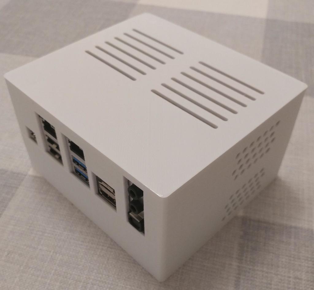
This is a compact and streamlined case for the [Odroid H2](https://www.odroid.co.uk/ODroid-H2). The case consists of two parts, with two variants available for each half. The bottom section can accommodate two 2.5" hard drives or be used in a shorter configuration. The top half offers an option to use built-in buttons or an external power button. The case measures 132mm wide by 117mm deep. The storage variant stands at 75mm tall, while the non-storage version is 56mm tall. All walls are 3mm thick, making the case sturdy and robust. The case features vents for fan-less cooling, as there is no space to install a fan. It is designed around the Odroid H2 board and secured using four 3mm x 50mm chipboard screws. ## Parts * h2-short-base.stl: Short form factor base with no storage support * h2-storage-base.stl: Storage form factor base with support for two 2.5" hard drives * h2-storage-hdd-mount-a.stl: HDD mounting bracket * h2-storage-hdd-mount-b.stl: HDD mounting bracket * h2-top.stl: Top half with external power button * h2-top-v2.stl: Top half with onboard buttons and LEDs support * button-lever.stl: Onboard button actuator * button.stl: Front buttons that interact with the lever ## Using the Onboard Buttons The second top variant supports using the onboard power and reset buttons. These can be activated from the front of the case, where two buttons interact with levers to push the onboard buttons. The buttons are assembled onto the levers, which simply push together. The buttons should then be slotted through the case so that the pivot hole of the lever aligns with the holes in the button supports and the button protrudes from the front slightly. A 25mm 3mm shaft is then placed through the supports and button lever pivots and secured in place using a 25mm M3 bolt or a 3mm by 30mm chipboard screw. There are five slots in the case to make onboard LEDs visible, which can optionally be filled with clear epoxy resin (or similar) to form light pipes. ## Using an External Power Button One top variant does not use the onboard power button. Instead, an external power button needs to be connected to the GPIO header and mounted on the case. There is a hole for a standard 5mm tactile switch on the front of the case. Follow the Odroid instructions for creating an external power button and glue it to the front of the case. Depending on the color the case is printed in, onboard LEDs might be visible through the case. ## Hard Drive Mounting The two 2.5" hard drives are mounted on two rails either side, which are then screwed to the bottom section of the case. The two rails snap onto the sides of the hard drives, each with four M3 x 5mm cap head screws in the normal side mounting holes, which the rails slide over. Once the rails are attached to the hard drives, the whole sub-assembly can be aligned over the two studs on the base and secured gently using a 2.5mm x 15mm chipboard screw. You will need some small SATA data and power cables as there is not much room in the case. I used some 10cm flexible SATA data cables. The SATA power cables were custom made, from a stock Molex to SATA power cable cut down to 10cm and re-terminated with the four-pin 2.54mm pitch JST XT connectors which the Odroid H2 has on board. ## Source Source FreeCAD models: https://gitlab.com/intrbiz/3d_printing/tree/master/Odroid%20H2%20Case
With this file you will be able to print Odroid H2 Case with your 3D printer. Click on the button and save the file on your computer to work, edit or customize your design. You can also find more 3D designs for printers on Odroid H2 Case.