-OLD- US/IE Rigid Middle Bracket Add On for Mostly Printed CNC - Camar0
thingiverse
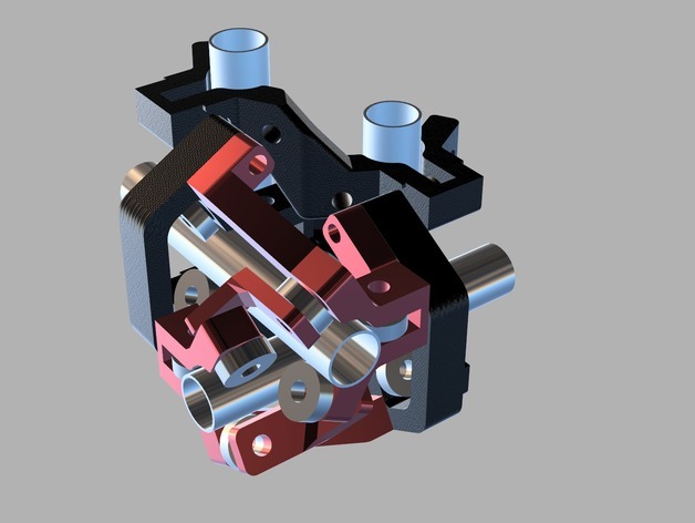
This part is outdated due to the new design, so it only fits if you have the old parts. The original user Camar0 deleted their account and removed all of their designs, but I found an archive of these files and am simply providing them to the community here again. This make from user markdoll01 has excellent photos showing the correct assembly and bolt orientation: http://www.thingiverse.com/make:186314 Original Description: This add-on makes the middle assembly stiffer, allowing it to cut more aggressively before the tool begins to chatter. It also simplifies squaring your machine since it holds the middle assembly square from the moment it is installed. In comparing to the stock machine, higher travel speed and cutting speed have been confirmed in real-world testing with the add-on parts. Internal testing was performed on a full 5' x 5' area with a very aggressive acceleration on 12.5v dc. The machine did not need any additional squaring after adding these parts as the middle z no longer flexes. I will be cutting this weekend and will post the results. Updated Assembly STL is also posted so you can see how everything fits together in Thingiview or on your device. Do not print the assembly! *11/3 Update - IE Parts posted and needs tested. Please post your Make once you have a chance to build it. *11/1 Update - The Outer Bracket has been uploaded. The spacer for the bearing was added vs. what I had in the rendered images. I've printed / installed the 2 middle brackets and outer couplers and the difference is night and day. With 17" rods in the X Y spots previously, I could bend the middle z all over the place. As far as I can tell with this setup it is completely rigid. I have separate mods that I'm working on that will be posted but this one is good to go. Note: The 'Middle Ends' still get used with this setup but were not drawn in to this CAD file shown in the rendering. 12/30 update: The IE edition has been checked and an STL has been uploaded (IE Middle Assembly CHECK.stl) allowing you to look down the bearings to see that everything should line up. To check it, I reassembled the middle using a fresh download of the rigid Z and middle ends and kept the previously aligned middle couplers. If your print has the bolt holes under 8mm, you need to open up the holes. The stock MPCNC bolt holes were 8.1mm and my parts match Allted's bolt holes. Please let me know if you still have concerns with the IE parts. There have been two reported builds where the IE fit perfectly. Another had to open up the holes to 8mm to get things to fit okay. I don't have an IE machine but have done my best to ensure the fit and function by creating a full IE assembly in CAD using Allted's shared STL parts aligned down to 0.01mm. 12/4 update: There have been a total of 5 known rigid middle add-ons built, and everyone has been very happy with the very noticeable added rigidity. There have been US and international builds tested on both CNCs and 3D printers. At this point, I highly encourage all MP CNC users to give it a shot. When I first installed my add-on parts, I couldn't believe how much stronger the middle felt. For a roughly $20 add-on with hardware and bearings, you will not find a better bang for your buck. Over 40 hours of engineering went into the design, which in itself is an amazing value that you can just download the end parts free. Cheers! 11/28 update: Cut out a Rudolph head at 20mm/s 5mm doc in plywood with no chatter. The end result can be seen in my builds. I tried to take a video but my battery died during the cut. I will be bumping up my driver current from 1.54a to 2.2a per motor and bringing the voltage up from 12.5v to around 40v DC next and see if I gain anything in rapids or cutting speed. 11/27 update: Just had a chance to make my first test cut. Everything went great. I took 1mm off the side of a 2x4 at 9mm depth with no problems. I will do more testing this weekend and post up the results. 11/25 update: The machine is assembled with all mods and moves at up to 19,000 mm/min currently with a very aggressive acceleration on 12.5v DC.
With this file you will be able to print -OLD- US/IE Rigid Middle Bracket Add On for Mostly Printed CNC - Camar0 with your 3D printer. Click on the button and save the file on your computer to work, edit or customize your design. You can also find more 3D designs for printers on -OLD- US/IE Rigid Middle Bracket Add On for Mostly Printed CNC - Camar0.