OLED remote mount for Nullbits Scramble
prusaprinters
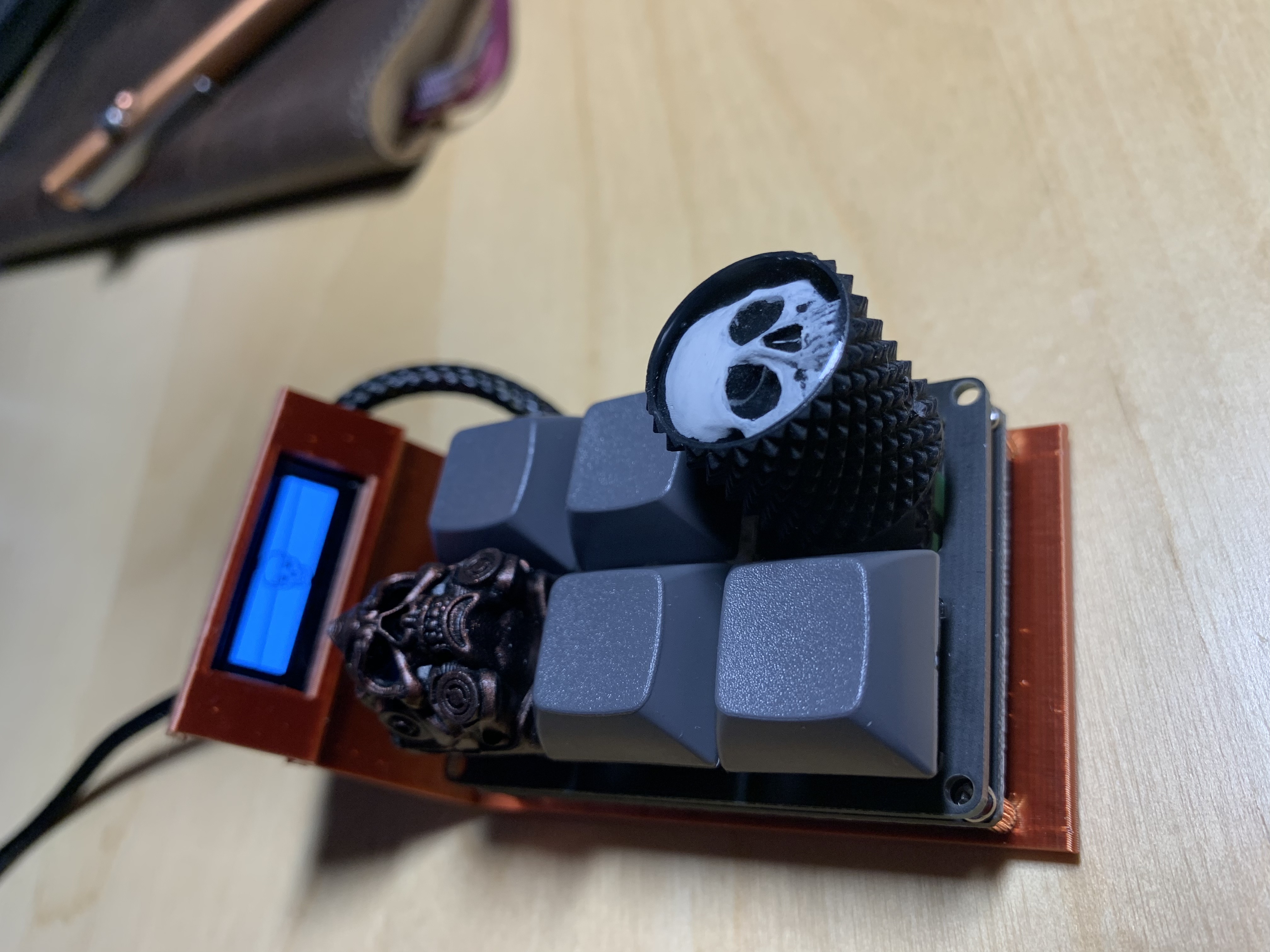
<p>Nullbits has a 6 switch macropad with options for encoder and OLED ( 128 x 32 ).</p><p>The scramble PCB layout however locates the I2C ( for the OLED ) through-hole vias in a location that if populated directly (i.e mounted onto PCBA ) will prevent access to install two of the key switches. I wanted to retain the use of these switches. So I created this solution which remote mounts the OLED over the USB port. It is meant to replace the bottom FR4 board that comes with the scramble. </p><p>This solution will require effectively replacing the 4-pin 2.54mm header provided with the OLED with a wired solution.</p><p>EDIT: Added optional 128x64 oled screen version. </p><h3><strong>Print instructions</strong></h3><p><strong>Resolution:</strong> 0.2</p><p><strong>Infill:</strong> 100%</p><p><strong>Supports: Yes ( maybe , depends on bridging ). Should only be needed on framing portion for OLED display.</strong></p><p>NOTE: Print on side, where slot for 90 degree header is orientated towards the top</p><p> </p><h3>BOM:</h3><ol><li>Scramble macropad</li><li>OLED for scramble</li><li>This model printed</li><li>4-pin 90 degree 2.54mm header</li><li>4-pin 2.54mm female to female dupont cable</li><li>(optional) heatshrink</li><li>(optional) braid</li></ol><p> My approach was to :</p><ol><li>Solder the 4-pin 90 degree 2.54mm header onto the OLED with the pins orientated across the OLED PCBA</li></ol><figure class="image"><img src="https://media.prusaprinters.org/media/prints/77298/rich_content/6ec96dd3-7aa3-455a-8b06-2d8c97ff2f01/aec4b59a-8aaf-4b9a-8e82-ab1c5073c038.jpeg#%7B%22uuid%22%3A%2216c1cb6d-1b7e-41fd-8ef9-442d5f6556c3%22%2C%22w%22%3A3024%2C%22h%22%3A4032%7D"></figure><p>2. Place assembly into the OLED mount on the print</p><figure class="image"><img src="https://media.prusaprinters.org/media/prints/77298/rich_content/6cac23e0-168b-40b0-97b4-2c2949fa8a1c/28833539-bd9f-42cc-9454-a4d36ca1bfd9.jpeg#%7B%22uuid%22%3A%22b2b50885-bd67-4005-993b-f7a5125606bf%22%2C%22w%22%3A4032%2C%22h%22%3A3024%7D"></figure><p>3. Cut dupont cable to length. ( approx 11.5 cm fro tip of connector to end of wire )</p><figure class="image"><img src="https://media.prusaprinters.org/media/prints/77298/rich_content/53428ea9-9811-4f8b-a469-34fd3d54c031/87067822-d79d-434a-ad82-bcef0677f5f9.jpeg#%7B%22uuid%22%3A%2247f8dadd-883e-44bc-8c74-cfde3bfbb120%22%2C%22w%22%3A4032%2C%22h%22%3A3024%7D"></figure><p>( NOTE: Attach optional heatshrink and braiding at this point , if you are using any )</p><p>3. Solder dupont cable ends to VCC, GND, SDA and SCL.</p><ol><li>Note order of cabling , this will need to match the order on the OLED</li><li>I used the following color code corresponding to the cable I purchased and the orientation of the signals on the header:<ol><li>White - GND ( usually denoted with a triangle on the connector )</li><li>Yellow - VCC</li><li>Black - SCL</li><li>Red - SDA</li></ol></li><li>Run cable between the underside of the scramble PCBA and the print.</li></ol><figure class="image"><img src="https://media.prusaprinters.org/media/prints/77298/rich_content/645d5c81-beea-40c7-925b-62f49c2acc7c/2d893214-e544-4528-95d8-ca5981f1fbaf.jpeg#%7B%22uuid%22%3A%226adb10b2-ab06-4c40-bc06-d0205d9510aa%22%2C%22w%22%3A4032%2C%22h%22%3A3024%7D"></figure><p>4. Attach the female connector to the 4-pin 90 degree header.</p><ol><li>Make sure to place pin 1 ( GND) onto GND header pin ( silked on the Nullbits branded OLED , YMMV )</li></ol><p> </p>
With this file you will be able to print OLED remote mount for Nullbits Scramble with your 3D printer. Click on the button and save the file on your computer to work, edit or customize your design. You can also find more 3D designs for printers on OLED remote mount for Nullbits Scramble.