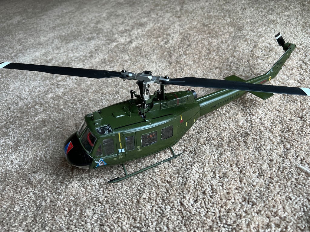
OMP M2 conversion, Revell 1:32 scale Huey
thingiverse
NOTE: This is still slightly a work in progress. Two of these have been built and they both assembled and flew fine but this is also a fairly complex project so expect a small amount of trim work to make everything fit. OK, on with the fun! This project creates an internal chassis and related parts that allow the OMP M2 R/C helicopter (regular or Explore version) to mount inside the Revell 1:32 scale Bell UH-1A "Huey" helicopter. In addition to the printed parts, you will need 10X small flat head sheet metal screws, a length of <1mm music wire (for the battery hatch hinge) and a pair of small square super magnets (to hold the battery hatch closed). Note that the "Explore" version of the M2 is $100 less expensive. It is currently identical to the regular M2 except that the servo cases are plastic. Battery access is through the battery hatch, which also carries the skids. Note that the stock battery will probably not fit. The preferred battery is the Gens Ace "Gens Ace 3S Lipo Battery 700mAh 11.1V 60C 3S1P", available many places including Amazon. With some battery wire "training", this battery will fit and can fly the conversion for >10 minutes with no reserves. I fly for 7 minutes and land with ~30% remaining. A word about glue.... The only thing I have found that actually produces a fusion bond with PLA is "IPS Weld-On 3 Acrylic Plastic Cement", available from Amazon. Technically, it is a solvent, not a glue. It does not fill gaps at all so parts need to be in contact with each other. It also works well with styrene and I used it for all gluing for this project. However, it is VERY volatile (thinner than thin CA) and has a boiling point close to room temperature. It also attacks EVERYTHING so be VERY careful not to get it on anything you do not want to glue. I use a small pipette to apply it. Make sure that you do not invert the pipette with glue in it because your finger heat will boil the glue, which then can come shooting out of the pipette. Don't ask me how I discovered this ;) NOTE: When gluing the body halves together, DO NOT glue the tail halves. The tail motor is secured to a piece of 0.030" aluminum that is shaped to fit between the halves of the tail. It extends from the top of the tail motor to at least 3/4 of the way to the boom and is held in place with some small sheet metal screws through the tail and aluminum. I used two on each side. Tail motor wires exit through a hole in the rear of the tail boom. You can enlarge the hole where the tail skid was supposed to mount. The screws used and shown in the photos are from this screw assortment: https://www.amazon.com/gp/product/B07X3X63ZK/ref=ppx_od_dt_b_asin_title_s02?ie=UTF8&psc=1 CHASSIS ASSEMBLY 1. Insert the music wire through the battery hatch and trim so it protrudes on either side. Assemble the two chassis sides and the battery hatch and screw the chassis end adapter to the sides with four small flat head screws. As you tighten the screws, make sure the chassis sides are even and level and the battery hatch can open and close. Note that the photos show an older version of the rear adapter that had screw holes but was glued in place. The current design uses countersunk flat head screws but can be glued if desired. 2. Place two square super magnets that will fit the pockets in the end adapter and the battery hatch together on either side of a small piece of wax paper. Apply a SMALL dot of Urethane (Gorilla) glue to the center of each magnet pocket, drop the magnet pair into the end adapter pocket and close the hatch on the pair. Let the glue dry, open the hatch and remove the wax paper. Note that the current design has the hatch magnet on the inside surface of the hatch and the magnets are in contact with each other. The photo shows an older version where the hatch magnet was on the outside. 3. With the two halves of the heli body glued together, cut the hole in the belly. The idea is that the mounting strips will be glued to the inside and mate with the chassis for a flush fit with the belly. The best way to glue the mounting strips in place is to have them screwed to the chassis so they are aligned correctly. This can be tricky... do not let glue get between the strips and the chassis flanges! The belly has a compound curve to it and I did not totally duplicate it on the mounting strips so the fit is not exact but it should be close enough. 4. Install the two skids on the battery hatch and secure with small flat head screws. Gently place the skid tubes on the skids and glue in place. 5. Glue the battery stop into place. It glues to the vertical edges of the chassis and acts as a buffer between the end of the battery and the motor bell. 6. Disconnect the pitch control links and remove the rotor and hub from the mainshaft. Remove everything from the M2 mechanics including the tail boom support structure. All you are using for this conversion is the basic mechanics and the tail motor. When you remove the screws, keep track of where they go because you will be re-using them. On each side, one screw is longer and has coarser threads. 7. Slide the mechanics into the printed and assembled chassis and secure with the original screws. The printed holes may be a bit small.... it depends on your printer.... but they can be threaded in. 8. Relieve the area around the mainshaft on the top of the body so the swash plate and linkages can fit through from below as the chassis is inserted through the belly. You can use the photos as a rough guide for where to cut the body for the linkages and swash plate. TAIL ASSEMBLY 1. Fabricate a long wedge shaped piece of 0.03" aluminum for the tail motor mount. The upper end will need to be drilled to pass the original tail motor mounting screws. Also drill a larger center hole to clear the motor shaft. 2. Cut the top of the Huey tail assembly off so the motor trim and spacer parts seat against the upper end of the tail with the aluminum piece positioned between the tail halves. 3. Slide the aluminum piece into place and drill small holes through the tail halves and the aluminum piece. Secure it with small flat head screws. If the screws bite into the aluminum and the tail halves, the assembly should be quite strong and stiff. 4. Enlarge the existing hole in the end of the tail boom so the wires and connector pins can pass and thread the wires into the tail boom. FINAL ASSEMBLY 1. Connect the tail motor wires and gently work the chassis through the belly hole and into place. Secure with six small flat head screws. 2. Reinstall the rotor system and reconnect the pitch control links. CONTROLLER SETUP and RADIO 1. On the M2 flight controller, reduce the cyclic gyro gain about two clicks. The tail gain can remain as-is. On mine, with the added mass of the scale body I had a gentle oscillation in a hover and this will stop it. 2. If you have a multi protocol radio or the OMP radio, you can fly the heli using the OMP protocol. This enables telemetry if you are using a multi protocol radio but the preset (and non-changeable) head speed is a bit high if you use the Evo blades. For full control over pitch and throttle curves, plug a pre-bound Spektrum satellite receiver into the flight controller. You can mount the satellite with double sided foam tape under the rear servo. BATTERY FIT AND INSERTION You will need to slightly extend the battery lead from the controller. Extend it just enough that you can grip the connector as you plug the battery in. Too long and the wires will not lay neatly in the nose with the battery inserted. I extended mine about an inch. The battery inserts with the power and balance wires to either side. You will need to dress the wires so that as the battery is inserted, the battery wires cross over the front of the battery and the connector ends up about midway between the sides of the nose. A piece of tape on the rear of the battery will act as a pull tab to make removing the battery easier. FLYING If you reduce the cyclic gyro gain (see "controller setup" above), you should find that the M2 flies the same with the body as without it. It flies fine with the stock blades, but I swapped the stock blades for a set of blades from the M2 "Evo" version. They are about 10mm longer and look a bit more "scale". They also allow you to fly at a lower head speed. FINAL NOTES For the purists out there, yes I am aware that the tail rotor is on the wrong side ;) I planned to reverse the main motor rotation, flip the blades over and put the tail rotor on the left side like the full scale heli. However, that would require reversing the rudder gyro sense and the only way I could see to do that was to physically invert the flight controller. So for now it stays on the right side. It MIGHT be possible to put the tail motor on the left and reverse the tail rotor so it blows to the right. The way it mounts to the tail makes it possible do mount it on either side. I'm also looking for more scale appearing blades. Something 190mm or 200mm long and narrower chord would look better. But for now I have painted the Evo blades flat black and they don't look too bad at all. Mine is painted with Tamiya acrylic over the Tamiya grey primer. It looks good and airbrush cleanup is easy with alcohol. But it is sensitive to alcohol so I have to be careful around alcohol.
With this file you will be able to print OMP M2 conversion, Revell 1:32 scale Huey with your 3D printer. Click on the button and save the file on your computer to work, edit or customize your design. You can also find more 3D designs for printers on OMP M2 conversion, Revell 1:32 scale Huey.