One Handed Soldering Tool
thingiverse
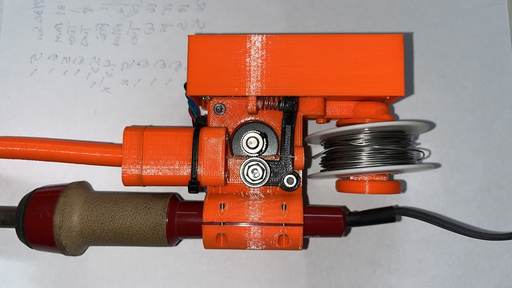
First, this is a derivative of RoboticWorx device. Credit for the original idea and design all goes to him. The original write-up on the project is here: ttps://www.roboticworx.io/p/build-a-one-handed-soldering-tool If you’re going to assemble one of these devices, you’ll need to make reference to RoboticWorx original writeup for many details. The original design did not fit my soldering iron, and I wasn’t inclined to create a PCB with all of the SMD parts. So I made some changes along the way. I used a Seeedstudio XIAO. The circuit only needed a couple of output pins, and the XIAO already has capactive touch input capability. I also was OK with having a 5V USB cord along with the soldering iron cord, so I went with a USB-in to 12V out DC to DC up-converter. This way I was down to 6 components. the 5V-12V converter, the XIAO, the Pololu driver, and 3 capacitors. Rather than try to come up with a custom PCB, I like to use Vero boards which have traces running vertically along the board and hand-placed wires for horizontal connections. I wasn't sure of the speed needed so I added a Pot to be able to adjust from 50 to 100, vs. the fixed speed of 75. A schematic and a cut/jumper diagram for the VeroBoard is included in the attached files. As stated above, the original design didn’t work with my soldering iron. So I used PrusaSlicer to modify the main motor mount (motor_mount.3mf). I cut off the soldering iron mount and added some mounting holes. This allows for different clam shells to clamp in the soldering iron. I also needed to extend the solder tube out, so Extruder Extension.stl does that. The extra side holes where originally intended to attach the “Forward” and “Backward” touch control plates. But after assembling and trying out various locations, the 2 large screws in the PCB cover turned out to be a much more ergonomic location. The “Forward” touch screw is convenient, and the “Backward” is out of the way since it is less frequently needed. I used PETG throughout although the only part that might really need PETG is the solder tube. The .gcode files are all set up for a Prusa MK3 with PETG Prusament. Most items don't need supports. The Arduino sketch I used is for the Seeedstudio XIAO and includes code for the speed adjustment pot. Two changes I am likely to make in the future are: (1) put the touch sensitivity back at 850, and (2) add a 5 second start-up delay in Setup: delay(5000); Seems like sometimes there is a brief “feed” when the device is powered on. Files: Motor_Mount – this is RoboicWorx original mount of the motor assembly. If you use a soldering iron similar to his, then use this. Otherwise, use my Motor_Mount.3mf plus Iron_Mount.stl and Iron_Mount_Cover.stl for Ungar-style soldering irons. Motor_Mount.3mf – this is a cut-up and modified version of the original Motor_Mount to accept different soldering iron designs. It requires Iron_Mount.stl and Iron_Mount_Cover.stl to actually mount the soldering iron to it. Iron_Mount.stl – attached to the modified Motor_Mount to accept a different soldering iron. Iron_Mount_Cover.stl – clamps the soldering iron in place and allows for some forward/back adjustment of the iron and thus the tip. Solder_Tube.stl – long snout for the solder to feed out to the tip of your soldering iron. Extruder_Extension.stl – since my Ungar soldering iron is longer than the original, this spaces out the Solder_Tube so the end meets the tip of the iron. Lever_Arm – spring arm to mount the bearing. PCB Spacer Plate.stl – spaces the PCB off from the main unit and insulates it from the Stepper Motor. Washer.stl – slides over the post that the solder roll sits on. Solder_Roll_Cap.stl – attaches to the end of the post that the solder roll sits on. This is RoboticWorx original cap. I have a slightly different cap. Either can be used. End Cap.stl – my end cap for the solder roll. Potentiometer Extension.stl – use this along with the cover if you decide to use my VeroBoard PCB. Cover.stl – cover for the PCB. Solder Feeder Vero Board.PDF – if you decide to use a Vero-board for your PCB, this is the layout for parts, trace cuts and jumper wires. Solder Feed Schematic V2.PDF – schematic for the revised controller.
With this file you will be able to print One Handed Soldering Tool with your 3D printer. Click on the button and save the file on your computer to work, edit or customize your design. You can also find more 3D designs for printers on One Handed Soldering Tool.