Onewheel Modular Battery Display Flight Fin Spacer Base (With Fuse, XT90 VnR Port & XT30 Accessory Port)
myminifactory
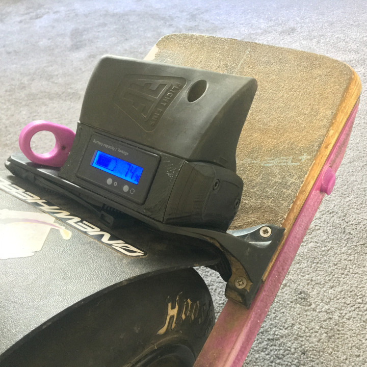
DO NOT ATTEMPT THIS PROJECT IF YOU DO NOT HAVE ANY ELECTRICAL EXPERIENCE. TAKE ON THIS PROJECT AT YOUR OWN RISK! READ THE INSTRUCTIONS COMPLETELY BEFORE ATTEMPTING TO MAKE SURE YOU'RE COMFORTABLE WITH THE PLANS LAID OUT THIS MOD WILL REQUIRE YOU TO ALSO ALTER THE FLIGHTFIN MOUNT. ------------------------------------------------------------------------------------------------------------------------------------------------------------------------------------------------------------------------------------------------------ This model is designed to fit on the FullFlight system.https://www.flightfins.com/product/fullflight-pro/ If you've modded your battery, extended it or it's just not matching what the app says then this print will allow you to add a battery capacity display to the Onewheel so you can more reliably measure your juice as you go. V3 now allows you to add modules to the side. Currently a headlight module is available to build so you can unload an ungodly amount of light to see even in pitch black. https://www.myminifactory.com/object/3d-print-173156 This also requires you to tap into the battery wiring to read the voltage. You can follow SonnyWheel's VNR guide below to see how you can use Posi-Taps to achieve this.https://youtu.be/vfBlp6pa9hk?t=1m31s Please be aware shorting theses wires will cause damage to the Onewheel that will not be covered by warranty so do not attempt this if you're not comfortable working with electronics. The display itself can be programmed for various battery types and capacities. For my XR I set my mode to L-15 (15s for a 63v lithium ion config) however for a V1 or Plus you may need a different setting that matches your boards battery type and voltage. For a wiring diagram please refer to the images for how mine is setup as an example. BOM 1x Battery Display : https://www.amazon.co.uk/dp/B07DVSTY59 4x M5 70mm Bolts : https://www.amazon.co.uk/dp/B07X8Q73SK 4x M5 Serrated Flange Nuts : https://www.ebay.co.uk/itm/121229896627 1x SAE Connector Extender : https://www.amazon.co.uk/dp/B08L3GSGC3 1x XT90 Male Connector : https://www.amazon.co.uk/dp/B07NW9RX9M 1x XT30 Female Connector : https://www.amazon.co.uk/dp/B06XPTXFW9 2x M4 10mm Brass Threaded Inserts : https://www.amazon.co.uk/dp/B08FX61DT2 2x M4 30mm Allen Socket Cap Bolt: https://www.ebay.co.uk/itm/221872591770 2x 20A Blade Fuses : https://www.amazon.co.uk/dp/B07ZSWXRH2 2x 16-14 gauge Female Spade Connector : https://www.amazon.co.uk/dp/B07M7N7LQR 1x 16 gauge wire : https://www.amazon.co.uk/dp/B07FN9G27L TOOLS BIG BRAIN! (Galaxy brain or more will suffice) A 3D printer, I think that's a given. Wire crimper / stipper Soldering Iron Heat shrink Allen keys and screwdrives Hammer (yes you may need this) Multimeter Hot glue gun Coping saw Bolt deburing tool (or somehing to repair M5 threads) Drill Instructions (starting at the image with the parts laid out) 1. Organise the parts 2. With a soldering iron press the 2 threaded inserts into the side of the spacer. You can place one of the 20A fuses in the blanking plate as it will be the spare. 3. Cut the SAE cable so that about 100-150cm of cable is a available for one side which will be the spacer side. Thread the wire in through the large hole in the back of the spacer then thread the red wire through the bottom right hole that leads out the right of the spacer. Strip a bit of insulation off the red wire. Remove the boot on the female spade connector then crimp that over thered wire. 4. Add some hot glue to the red wire that is exposed out the right and some around the base of the spade connector. Press the connector into the spacer until it is almost flush with the bottom of the insert. If the glue cools or it doesn't fit use the soldering iron to heat press it in. Take 100mm or red 14 gauge wire from the other end of the SAE connector we left earlier and crimp the other female spade connector to that. Replicate the glue procedure and press that in too with the red wire poking back into the spacer. You should now have a red and a black wire poking out the spacer in the middle that you can easilly work with. Once cooled test fit the blade fuse to see if it fits. 5. Solder 100mm of 16 gauge wire to the XT30 connector and thread that through the XT30 slot into the spacer. 6. Apply some hot glue to the back of the XT30 and the wires then quickly press it into the slot. 7. Cut 200mm or red and black 14 gauge wire from the other end of the SAE connector as before and solder those to the XT90. Thread that though the XT90 hole, through the internal channel and up into the sparer. 8. Test fit and see if the XT90 fits snuggly inside. If not try sanding down the connector walls. Once it's sliding it a bit pull it out a bit and insert the female end of the connector to keep it rigid. Insert some hot glue into the XT90 hole then press the connector in. If it resists tug on the 14 gauge wire and use a hammer to tap it down till the male connector walls are flush with the edge. 9. Take all 3 of either colour wire and trim them down so they're all the same length ready to solder. To make things easier you can use some heat shring to keep them in line. 10. Solder them together so the red are all together and the black are all together too. 11. Solder the battery display connector to the black and red groups and make sure they're all heat shrinked to prevent shorting. 12. Gently press the wires down into the spacer and keep the battery display connector petruding 13. Before adding the display take your multimeter and check all the postive connections have continuity as well as the negative. 14. Also make sure that positive and negative are not shorting. 15. Connect the battery display and slot it into its recessed hole. You can now take the blanking plate and the 2x 30mm m4 bolts and prepare to close that up. You can add some 3mm adhesive foam around the XT30 port in the recessed channel to act as a gasket if you desire. 16. Tighten down the bolts. If they don't quite line up reheat the threaded inserts then try again. Don't overdo it or you might plastic weld the 2 together. 17. The spacer is now complete. 18. As is the SAE connector will not fit through the full flight system. 19. Bolt the SAE Jig to the full flight system and get a 10mm drill bit. 20. Drill out the top small hole. 21. Remove the lower bolt and drill the low small hole. 22. Use a coping saw blade to connect both the holes. 23. Remove the jig and use a file to clean up the widened hole. 24. The SAE connecto should now easilly thread through. 25. Before attaching the spacer you may want to fill the hole with the SAE connector coming out with hot glue or silicone to help keep water and debris out. 26. Using the longer 70mm bolts and serrated nuts connect the flight fin, spacer and fender together You may need to trim the bolts down so they don't have too much excess thread. 27. Nearly there, looking fresh. 28. Remove the front footpad from your board and mount the fender to the board. Connect the other end of the SAE connector and then place the shield on too in order to see how it all fits. 29. Check there is a noticable gap still between your tyre and shield. If not the wire/connector might be petruding too much and needs adjusting. 30. With the other end of the SAE connector connected you can now see how much wire you need to connect up to the battery connector. I already had pre-spliced wires so just soldered them on with some excess just in case. Check the video by SonnyWheels mentioned earlier in the notes to see how to wire into this connector if you're unsure. I would recommend taking your time and not having the spacer connected during this. 31. Once all wired up put your footpad back on and remount the full flight system, connecting the SAE connectors and powering the board on. It should power on and present a readout on the battery display. You will more than likely need to calibrate this using the instructions to be in mode L-15. 32. Verify the voltage presented at the VnR port is also what the battery display is showing by switching modes. 33. Again, but in percent mode. 34. You're done. Congrats you didn't nuke your board!
With this file you will be able to print Onewheel Modular Battery Display Flight Fin Spacer Base (With Fuse, XT90 VnR Port & XT30 Accessory Port) with your 3D printer. Click on the button and save the file on your computer to work, edit or customize your design. You can also find more 3D designs for printers on Onewheel Modular Battery Display Flight Fin Spacer Base (With Fuse, XT90 VnR Port & XT30 Accessory Port).