OpenAstroTracker electronics box
thingiverse
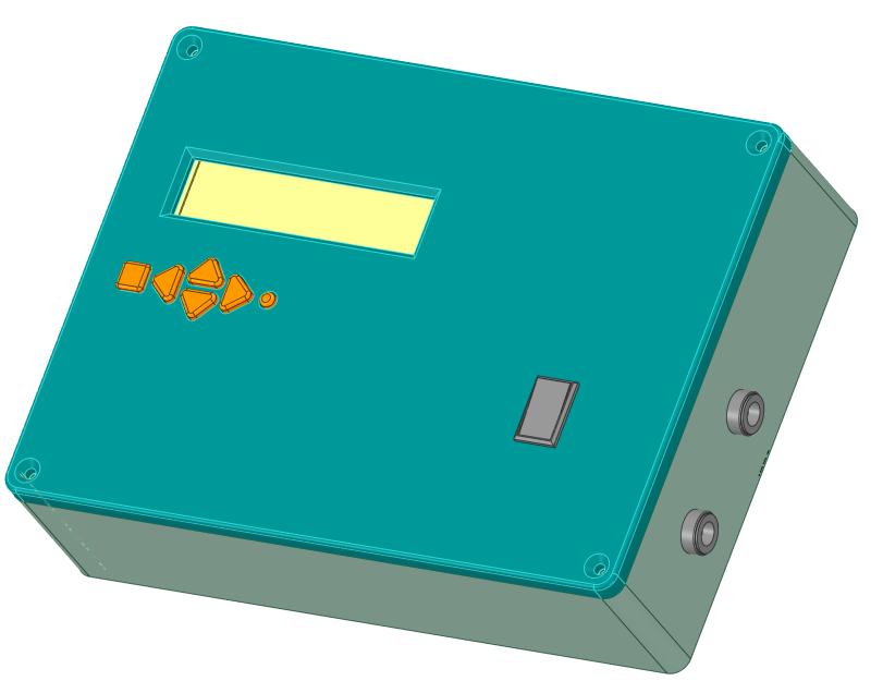
My version of a box for the OpenAstroTracker electronics, NEMA17. All the electronics are in one main box with a small connector box mounted on the OAT itself. The two are connected with rj45 patch cable / keystones. Note that this is probably pushing the rj45 cable to it's current carrying capacity as it is carrying the power to the steppers and not just data signals. Use at your own risk! The steppers are wired into the connector box using standard JST-XH sockets soldered to small pieces of veroboard. These slide into slots in the connector back. The conenctor box is mounted to the OAT 20x20 with M4x30mm & T-nuts. In the main box, the LCD/button shield is attached to the lid with 4 small screws, use an M3 nut as a spacer between the two PCBs of the shield. The Mega is just pushed onto the back of the shield. There are 2 holes for 5.5x2.1 sockets, one for 9/12v IN and one for (in my case) 8v OUT to my Canon camera. There are mounting clips in the base for a buck for this OP. There is a mounting point in the base for a small strip of veroboard. I use this as a central distribution point for V+ & GND. I solder Dupont sockets on the strip and use dupont pins for all connections as this is much easier to mess with and more robust than soldering wires direct to the various components. I have a mounting hole for a small rocker switch on the front panel, this switches the supply to the Mega so when power is connected, it only goes to the steppers, the Mega is switched on separately (and switched off before disconnecting the main power).
With this file you will be able to print OpenAstroTracker electronics box with your 3D printer. Click on the button and save the file on your computer to work, edit or customize your design. You can also find more 3D designs for printers on OpenAstroTracker electronics box.