OpenWhoop Parametric Micro Racing Multirotor Drone
thingiverse
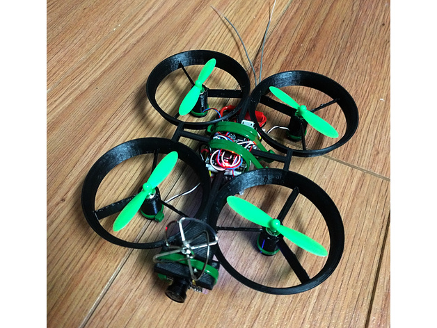
This appears to be a configuration file instructions manual for a 3D printing model, specifically a drone frame and camera mount. The document explains various parameters that can be adjusted in the config file to customize the design of the drone. Here's a summary of the key points: **Motor Settings** * `motor_diameter`: Self-explanatory * `motor_clearance`: Clearance around the motor holder for easy sliding in and out * `motor_height`: Length of the motor, with an additional 2mm to accommodate wire tucking * `motor_mount_gap`: Gap in the motor mount for tightening with a zip-tie **Rotor Settings** * `rotor_diameter`: Diameter of the propeller * `rotor_clearance`: Clearance inside the duct for the propeller (not an increase in radius, but total diameter) * `rotor_pod_fin_count`: Number of fins or struts to add to the rotor pod/nacelle * `rotor_pod_fin_angle`: Angle of the stators/fins, with default values based on BetaFlight settings **Duct Settings** * `duct_flair` and `duct_curve`: Parameters for calculating the curvature of the intake in the duct (exponential curve) **Quad Frame Settings** * `quad_frame_wheelbase_size`: Desired wheelbase size of the quad (diagonal max shaft to shaft distance) * `quad_frame_wheelbase_width`: Customizable aspect ratio of the quad **Hex Frame Settings** * `hex_frame_wheelbase_size`: Diameter of the "circle" for the hex frame's wheelbase **General Settings** * `wall_thickness`: Thickness of walls in the duct, etc. * `motor_wall_thickness`: Thickness of motor holder and fins/stators (separate from wall thickness) * `frame_thickness`: Z-thickness of the inner frame structure * `cam_width`, `cam_length`, and `cam_angle`: Camera body dimensions and tilt angle * `cam_ant_width`: Width of antenna wire * `$fs` and `$fa`: Standard OpenSCAD settings for Circle/Arc resolution Overall, this document provides a comprehensive guide to customizing the design of the drone frame and camera mount using the config file.
With this file you will be able to print OpenWhoop Parametric Micro Racing Multirotor Drone with your 3D printer. Click on the button and save the file on your computer to work, edit or customize your design. You can also find more 3D designs for printers on OpenWhoop Parametric Micro Racing Multirotor Drone.