Oscilating Wobbler Engine
thingiverse
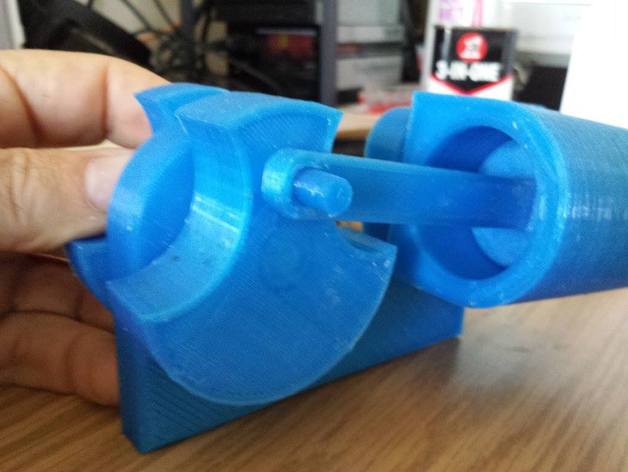
This is a revised version of the Pimboden engine. The connection rod pin was on the wrong side of the crank. I made the crank thicker, and increased the stroke (no replacement for cubic displacement, Heh!) to allow for more power in each revolution. You will likely not require the flywheel for the engine to run, but you may want to print and add it just for looks. Here is a short video showing the engine running with the original crank prior to my redesign:http://www.youtube.com/watch?v=DsSTE1BJaWI The model will require a pair of 608 Skate Bearings... or you could -=TRY=- a printed one like this:http://www.thingiverse.com/thing:43881 Instructions Print the body and fit a pair of 608 Skate Bearings. Sand the cylinder's port side smooth as possible, using a course grit sandpaper like 100 grid, then a fine like 180 or so. You want to be able to see NO light between the body and cylinder when the two are pressed to one another. Some air loss is ok, but for the best running engine that will run on a very low PSI of air, you want the fit to be light tight. Print and sand for fit the first Axle piece. If you want, you can also use smooth 8mm rod. A printed axle will not last as long, but works. It's entirely discretionary depending on if you intend to regularly run the engine, and for how long, for if you use a printed part or metal. Either will work. Insert the axle into the cylinder and glue with CA glue. Be SURE the axle does not protrude into the cylinder. Glue the connection rod into the bottom of the piston. Test fit in the cylinder. Sand with 100 and 180 grits until you have a good fit. When you put your finger over the cylinder port, and withdraw the piston quickly, you should hear that POP of vacuum sound. No Pop, no working. You want the fit to be good, but not too tight or the friction will prevent running. Again, some airloss is acceptable, it will just require a higher PSI to run. Sand the connection rod and crank pin for a slightly loose fit, but be sure to keep them fitted with a 90 degree angle. You are just looking for a "loose enough" fit. Glue the second axle into the crank. Be sure to allow enough stickout to go through the body and into the flywheel. You may want to scale the Z axls on the axle for additional length based on the flywheel used and how far you glue the axle into the crank. The axle need not be sanded and fitted fully into the crank but lots of room in the crank is provided should you choose to use a printed axle, or use another piece of 8mm rod. fit the bushing and locknut onto the axle for the cylinder. Don't CA glue the locknet yet, you'll need to test fit and test run the engine prior to gluing. Fit the crank to the connection rod and insert the axle into the crank. Attach the flywheel Secure the body to the base. Lubricate the cylinder/piston as well as the mating surface between the body and the cylinder. A good choice is something like a 3-in-One oil. You want something thin like a 1wt oil viscosity wise. The higher the viscosity, the more friction it can add to the engine and require higher PSI to run. Turn the crank to place the cylinder towards top dead center. Apply air pressure (start at 5-10psi and increase as/if necessary) to one of the port holes. Either one should work. If you switch the one you apply air to the engine will just turn the other direction. Once you are happy with the running of the engine, CA glue the flywheel and lock nuts (or leave it as a press fit) Enjoy. :)
With this file you will be able to print Oscilating Wobbler Engine with your 3D printer. Click on the button and save the file on your computer to work, edit or customize your design. You can also find more 3D designs for printers on Oscilating Wobbler Engine.