OtterVIS LGL spectrophotometer
thingiverse
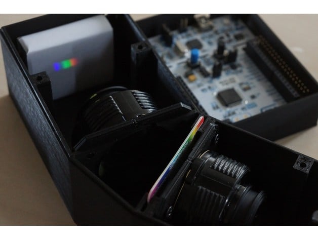
This is a 3D-printable spectrophotometer based on a TCD1304 linear CCD and standard 35mm camera optics. The resolution is ~1nm (the Na-doublet at 589nm is just exactly not resolvable). The total price of the components depends on how cheaply you can scavenge them on that auction site, but expect to pay something like this: Optics: 2x 10$, CCD: 10$, MCU: 15$, Grating: 3$, A few $$ for misc. parts. Total: ~60$ How I Designed This The design The spectrometer is a lens-grating-lens design: The diffraction grating is a cheap transmission grating slide. Both lenses are pentax SMC-M 50mm f/2, which are easy to find and cheap. The grating constant is 1000 lp/mm and the lower wavelength is chosen to be 380 nm as the lenses start absorbing here. From 760 nm second order diffraction starts to overlap so 760 nm is chosen as the upper limit for the spectrum. Inserting these values into the diffraction equation gives angles of diffracted light from 22.3°-49.5°. The center angle is 35.9°, which is the angle between the two optical axes of the lenses. The CCD (TCD1304) is 29.1 mm long and and with a bit of trigonometry we end up with an ideal focal length of 60mm for the focusing lens. A bit higher than the 50mm actually used, so a part of the CCD remains unused. How to construct the spectrophotometer Step 1: Print Download .scad files. If you have a different grating calculate the center angle and modify the parameter 1st in the file poly-definitions.scad Modify the files slit-holder.scad, and magnet.scad to fit your magnets. Make sure that the CCD-PCB matches the holes in the spectrometer box. Print everything. Mind you that the spectrometer box will take ~18 hours to print. Lenses Strip the lenses. Unscrew and remove the bayonett. Unscrew and remove the aperture coupling together with any screws you find. Unscrew front ring. Again remove any screws you come by. Remove the front lens group. Remove the aperture iris. Remove the lens barrel from the focusing helicoid. Reassemble the front and back lens groups. They should now look like this: Insert the lenses in the lens holders and secure them with some of the left-over screws. The linear CCD module The spectrometer uses a TCD1304 linear CCD driven by a ST Micro Nucleo F401. The firmware can be found here https://tcd1304.wordpress.com/ A computer running linux or macos is required to communicate with the CCD module. There's a 3rd party Windows client as well. Populate the CCD PCB. It should look like this: Insert the PCB in the spectrometer box using M3 hex-screws (don't use philips, it's hard to fit a screwdriver inside the spectrometer). Use 3 springs from ball-point pens between the PCB and the spectrometer wall. They will act as a primitive kinematic mount. The slit Fit the magnet into the slit-holder and cut a DE-razor blade to make a slit. Insert two 10mm M3 screws in the two lower screw-holes of the spectrograph (the holes will be inaccessible later). Mount the slit-holder with two 16mm M3 screws and two pieces of ballpoint-pen-spring. Assembly and focus Insert the lenses into the spectrograph and secure them using two M3 screws. Focus the slit using an autocollimation procedure: Place a small mirror after the focusing lens and a flashlight in front of the slit as show here: Use the reflection of the slit onto itself to focus. The grating Insert the grating slide. You will probably have to cut a few mm's of the sides to make it fit. You will now have something looking like this: You can now use a laser pointer to bring the CCD roughly into focus. Sample accessories Fit the magnets inside the magnet-holder: Secure it to the spectrometer: Assemble the cell-holder: Click it on the spectrograph: The light source Still a work in progress.. Focus the CCD Use different laser pointers to bring the CCD into focus. Focus first using a blue laser adjusting only the screws to the left. Then focus a red laser, adjusting the screw to the right. Do a few iterations until you don't see improvements. Each laser should produce the most narrow line possible: If you did everything properly, you should be able to make a recording of a CFL-lamp with greater detail than I have here: Parts list Hardware Linear CCD module (Nucleo F401re, TCD1304DG, CCD-PCB) check out https://tcd1304.wordpress.com or my HAD-project page https://hackaday.io/project/9829-linear-ccd-module 2x Pentax SMC-M 50mm f/2 A small assortment of magnets A DE-razor blade Diffraction grating slide (1000 lines/mm) Software Linux (any distro will do), macos (Sierra works, probably others as well. You can even use windows with Jens-Ulrich Fröhlichs java-based GUI. TCD1304 driver firmware for STM32F401RE (UART) GUI or CLI (UART) Both are available from tcd1304.wordpress.com For an Octave extended GUI visit http://science.jefro.de/
With this file you will be able to print OtterVIS LGL spectrophotometer with your 3D printer. Click on the button and save the file on your computer to work, edit or customize your design. You can also find more 3D designs for printers on OtterVIS LGL spectrophotometer.