Overly Complicated Stamp Dispenser
prusaprinters
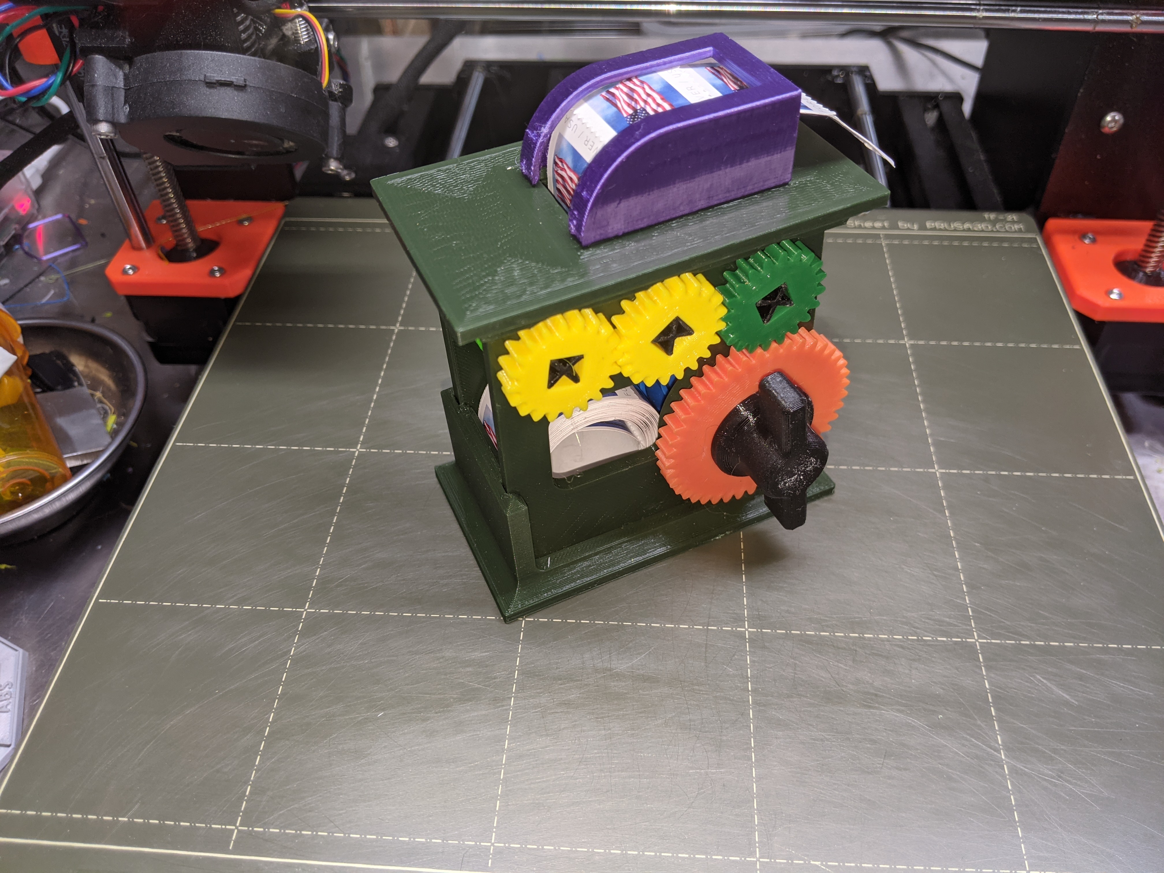
<p>Just decided to have some fun (in the spirit of Rube Goldberg) with a stamp dispenser for my desk. This dispenser is intended to be used with a roll of postage stamps; the width of the roll is approximately 25mm.</p><p>A bonus for me in doing this build was learning some new CAD skills, and finding out some new things about 3D printed gears (for example, I found that larger gear teeth worked better for this application).</p><p> </p><h4>How to Use</h4><p> </p><p>To use the stamp dispenser, place a roll of stamps into the pace behind the crank. Insert the first stamp upward into the rollers (a pair of tweezers held with this), and rotate the crank clockwise (as viewed from the crank side); continue cranking to advance the stamps through the top guide until a stamp emerges from the guide. The crank only needs to be turned a quarter-turn or so, and then reversed; continue this until the stamps advance as far as desired. Note that the crank is ratcheted, so it only turns the gears when turned in the clockwise direction.</p><p>When a stamp has been advanced through the guide it can be removed from the backing. Excess backing can be removed by tearing upward against the “tear bar” at the end of the guide.</p><p>Pro tip : If for some reason you need to back the stamps out of the dispenser, use a tweezers to rotate the stamp roll in reverse.</p><p> </p><h4>Assembly</h4><p> </p><p>See the "exploded view" to see how all the parts come together.</p><p><strong>Bottom and SideWalls :</strong> Start by assembling the Bottom and SideWalls. Before assembly, check the fit of the other components first, and de-burr the holes if necessary to enable a fit. Note that one side of each wall is slightly angled; begin by inserting the bottom corner of the angles side, and then rotate the wall down and into the slot on the bottom. Note the Bottom slots have “crush ribs” so this will be a tight fit.</p><p><strong>Top and RollerGuide :</strong> Next, insert the Slot Guide into the Top piece. Be careful not to push down on the “tear bar” at the front of the slot guide. Do NOT add the Top piece to the sides at this point.</p><p><strong>Roller Rings : </strong>The next step is to put the flexible “rings” onto the Roller pieces. Insert one ring onto each end of one Roller. Then insert two rings into the middle of the other Roller roller. (See photos.)</p><p><strong>Install Rollers and RollerGears :</strong> Now place one Roller between the side pieces, and insert an axle piece (44mm length) through the roller. Put a small RollerGear on each end of the axle to hold the roller in position. Repeat for the second Roller. Do NOT install the third small gear set at this time. (See photos.)</p><p><strong>Crank and Ratchet :</strong> Insert the 46mm length axle piece into the CrankHub. Insert the CrankHub into the RatchetGear, and then add the Ratchet to the Axle so that the Ratchet is inserted into the RatchetGear. Make sure the Ratchet is inserted in the proper direction (see CAD screenshot of the ratchet assembly).</p><p><strong>Spring :</strong> Now add the ratchet assembly and axle to the main piece, being sure to first put the Spring in place so that the axle goes through the Spring hub. Make sure the Spring is oriented properly (see CAD screenshot).</p><p><strong>AxlePlug :</strong> With the Crank axle fully inserted, add the AxlePlug onto the end of the axle.</p><p><strong>SpringPin : </strong>Next, insert the SpringPin into the hole opposite the crank, making sure it goes through the “eye” on the Spring.</p><p><strong>Link Gears :</strong> Use an axle piece (44mm length) to place the third pair of small gears in place (there is no roller for the third set of gears).</p><p><strong>Top assembly :</strong> Complete assembly by adding the Top assembly to the Sidewalls. Make sure the slot is over the Rollers.</p><p> </p><p>Once the dispenser is fully assembled and working, if necessary you can put a single drop of super-glue on one corner of each axle to hold the gears in place. </p><p> </p><h4>PRINT INSTRUCTIONS</h4><p> </p><p>Both 3mf and gcode files are provided for all parts. Note that the roller Rings are printed in “FLEX” (TPU); all other parts are PLA.</p><p> </p><h4>CAD</h4><p> </p><p>The OnShape 3D CAD files are here :</p><p><a href="https://cad.onshape.com/documents/f53ebb66a39b539fe753bf0e/w/1e7550586c5c7a0fe7b3e46e/e/48a3599296a4cb0703b68ef4">https://cad.onshape.com/documents/f53ebb66a39b539fe753bf0e/w/1e7550586c5c7a0fe7b3e46e/e/48a3599296a4cb0703b68ef4</a></p><p> </p>
With this file you will be able to print Overly Complicated Stamp Dispenser with your 3D printer. Click on the button and save the file on your computer to work, edit or customize your design. You can also find more 3D designs for printers on Overly Complicated Stamp Dispenser.