OWI-535 Adapters for Joint Potentiometers
thingiverse
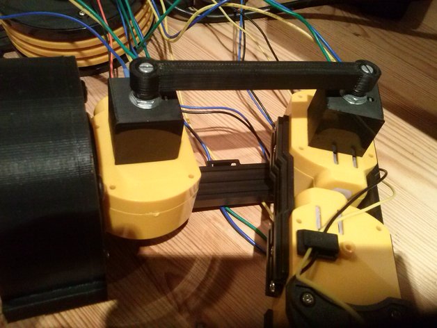
The OWI-535 robot is a 4+1 axis toy robot that's inexpensive but interesting. The basic kit is remote-control only where you run each axis with a thumb stick. There is a USB-kit that allows you to run the motors from your PC, and you can write little script-like programs, but it only amounts to timed moves. The problem is that to repeat a sequence over and over, you need joint angle feedback because timed moves will accumulate error with each move. The OWI-535 doesn't have any feedback sensors. I was inspired by this project. The set of adapters I've uploaded here allows you to mount potentiometers on joints 1 through 4, and a switch to detect the "open" status of the gripper. You install these by replacing existing parts on your OWI-535 with these using the same screws, and you don't have to modify the robot irreversibly. You can always put it back to factory condition if you like. I was working on an Arduino UNO-based control system which does the inverse and forward kinematics so you could jog joints 2 through 4 in X and Y (out/back and up/down) directions. However, I have let the project sit for a long time without the time to finish it, so I've decided to upload the parts so others might have a chance to build on it. The potentiometers are cheap "B5K" type purchased from Tayda. For reference, the overall length of the pot is 27.6 mm, the "mounting surface" to end of knob is 17 mm, knob diameter is about 6 mm, and resistance if 5k ohm. The switch for gripper open was purchased from RobotShop, part # RB-All-41 for a pack of 10. For reference, to control the motors I used the Adafruit Motor/Stepper/Servo shield kit (product 81, now discontinued unfortunately). It can be wired to control up to four 5V hobby motors. The motors in the arm are only 3V, so I made sure never to give it a command above 3/5 or 60% of full scale. Since it only has 4 outputs but the OWI-535 has 5 motors, I used a relay to switch the 4th motor output between controlling joint 4 or the gripper. You're never moving the arm when you're opening or closing the gripper anyway, so this works. If you'd prefer to use the USB kit to control the motors rather than an Arduino, then you can easily control the motors from C# using a sample C# project I wrote. Then you'd have to get the potentiometer and switch sensors back into C#, so you could use something like Phidgets. In C++ for Arduino, the forward kinematics (using joint angle readings from joints 2 through 4 to calculate the gripper position in X (out) and Y (up) relative to J2 center) is fairly simple: const float J2_TO_J3_MM = 90.0; const float J3_TO_J4_MM = 110.0; const float J4_TO_GRIPPER_MM = 88.0; // distance from J4 center to end of gripper fingers, when gripper open // What follows is the Forward Kinematics equations for J2, J3, and J4. // Note that point 0, 0 is considered to be the center of joint J2. // Positive X is horizontally away from the base // Positive Y is vertically up // What we want to calculate is the position and angle of the end of the // gripper fingers (when in the open position) angleSum = j2Radians; _j3Position.x = sin(angleSum) * J2_TO_J3_MM; _j3Position.y = cos(angleSum) * J2_TO_J3_MM; angleSum += j3Radians; _j4Position.x = _j3Position.x + cos(angleSum) * J3_TO_J4_MM; _j4Position.y = _j3Position.y - sin(angleSum) * J3_TO_J4_MM; angleSum += j4Radians; _toolActual.pos.x = _j4Position.x + cos(angleSum) * J4_TO_GRIPPER_MM; _toolActual.pos.y = _j4Position.y - sin(angleSum) * J4_TO_GRIPPER_MM; _toolActual.angleDegrees = radToDeg(angleSum); The inverse kinematics (calculating the desired J2, J3, and J4 angles to achieve a desired gripper X, Y, and angle position) are here: boolean Robot::inverseKinematics(coordTool toolSetpoint) { coord2D toolPosition = toolSetpoint.pos; float angleDegrees = toolSetpoint.angleDegrees; float angleSum; coord2D j4Position; // We have to do the Inverse Kinematic equations here. // The goal is to calculate the joint angles based on the given // position and angle. angleSum = degToRad(angleDegrees); j4Position.x = toolPosition.x - cos(angleSum) * J4_TO_GRIPPER_MM; j4Position.y = toolPosition.y + sin(angleSum) * J4_TO_GRIPPER_MM; // Now find polar co-ordinates of where J4 is float j2toj4 = sqrt(j4Position.x*j4Position.x + j4Position.y*j4Position.y); // dist. float j4AngleFromJ2 = atan2(j4Position.y, j4Position.x); // Quick check to make sure it's possible to reach if(j2toj4 >= J2_TO_J3_MM + J3_TO_J4_MM) { _toolSetpointValid = false; // nope... return false; } // Now imagine a triangle whose vertices are: // 1. the origin (center of J2) // 2. center of J3 // 3. some point along j2toj4 (call it P), such that P-J3 is perpendicular to j2toj4 // Calculate the length from the origin to P: float pDist = (j2toj4 + (J2_TO_J3_MM*J2_TO_J3_MM/j2toj4) - (J3_TO_J4_MM*J3_TO_J4_MM/j2toj4))/2.0; float pDist2 = j2toj4 - pDist; // Then calculate the angle between j2toJ4 and J2_TO_J3 float tempAngle = acos(pDist/J2_TO_J3_MM); float tempAngle2 = acos(pDist2/J3_TO_J4_MM); // Now we can calculate our angles float j2Radians = PI/2.0 - (tempAngle + j4AngleFromJ2); float j3Radians = PI/2.0 - (PI-tempAngle-tempAngle2); _j2Degrees = radToDeg(j2Radians); _j3Degrees = radToDeg(j3Radians); _j4Degrees = angleDegrees - _j2Degrees - _j3Degrees; _toolSetpointValid = true; return true; } The gripper control is as simple as "open until you hit the switch" and "close based on a timer". I'm sorry I don't have a more complete solution. That's where you come in. Can you find a use for this cool little robot? :) Print Settings Printer: Ecksbot Rafts: No Supports: No Resolution: 0.2mm Notes: Parts are designed to be easily 3D printable without support. How I Designed This OpenSCAD, source included.
With this file you will be able to print OWI-535 Adapters for Joint Potentiometers with your 3D printer. Click on the button and save the file on your computer to work, edit or customize your design. You can also find more 3D designs for printers on OWI-535 Adapters for Joint Potentiometers.