PanelDue 7i enclosure for printing on small print-beds (OpenSCAD)
thingiverse
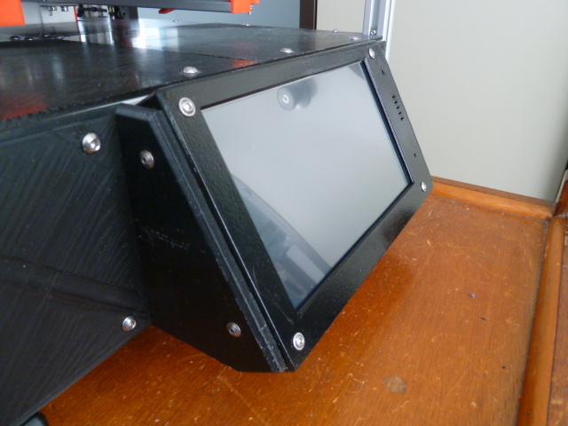
<h3>Introduction</h3> I recently purchased a PanelDue 7i for my CoreXY printer, seeking to break free from computer dependence. I initially thought the 7" screen would be most useful, but soon realized it wouldn't print an enclosure on either of my printers - the CoreXY has a 200mm x 200mm bed and the Anycubic Kossel boasts a 240mm round bed. This led me to get creative... <h3>Basics of the design</h3> I leveraged OpenSCAD to craft a complete enclosure that could be printed in two halves, then glued together later (or even in one piece if your print-bed is expansive enough). I designed it with the assumption that I'd need to glue the pieces together, fill gaps, and paint the enclosure for the finish I desired. <h3>Printing setup</h3> The first step involves printing a test jig to ensure it matches the holes on the PanelDue circuit board. If your printer is accurate, they will align perfectly; otherwise, use scaling in the slicer. Once you confirm the alignment, start printing the enclosure, applying the same scaling factors if necessary. Keep the correct-sized test jig as it will be essential during gluing. The pieces can be printed in one session by slotting them together in the slicer, but I found that the open ends of each half tend to distort and set into positions difficult to glue. To avoid this, print the braced versions, which must be done one at a time. Internal joining pieces were used to fix the two halves together for a smooth exterior. I've also included an STL file for external joiners, though they are untested - they might prove challenging to print nicely. You can use both internal and external joiners for added strength. <i>Note: The internal joiner in the photographs was originally L-shaped; after assembly, it fouled the LCD screen's side, so I had to cut it away, replacing it with a simple flat plate. This will still be more than strong enough if assembled and glued properly.</i> <h3>Assembly</h3> Both halves were located using the jig printed earlier, then clamped to 20mm aluminium angle extrusion to ensure perfect alignment of their sides and top. The joiner was clamped over the joint, ensuring all faces fitted snugly together. If you're using outside joiners, fit the aluminium extrusion inside the joint and clamp accordingly. Liquid "plastic weld" was painted generously over every seam, then left to harden. Once set, the aluminium extrusion was removed, and more plastic weld was painted over the other side of each joint. The second side was completed once the first had hardened. The jig was then removed, and the PCB fitted to verify everything was correct. <h3>Finishing</h3> Any gaps remaining after joining were filled with automotive body filler, then sanded flat. After a general check for lumps and bumps, the enclosure was sprayed first with plastic primer, then with a coat of black gloss. This was left to fully dry off before fitting the PanelDue PCB properly using M3 x 16mm screws. I used nylon washers under the nuts, but it's unclear if they were necessary. <h3>Mounting the enclosure</h3> The case features holes at each end for fixing it to brackets with M3 screws. Ensure the screws don't contact the PCB - there's just enough clearance for the M3 nut and a bit more. I've included an OpenSCAD file, "PanelDue_mount.scad", as a reference for designing your own brackets. An aluminium plate was used to close the base of the assembly and protect the PanelDue board.
With this file you will be able to print PanelDue 7i enclosure for printing on small print-beds (OpenSCAD) with your 3D printer. Click on the button and save the file on your computer to work, edit or customize your design. You can also find more 3D designs for printers on PanelDue 7i enclosure for printing on small print-beds (OpenSCAD).