Parallel Guide for Bosch POF 1400 or 1200
thingiverse
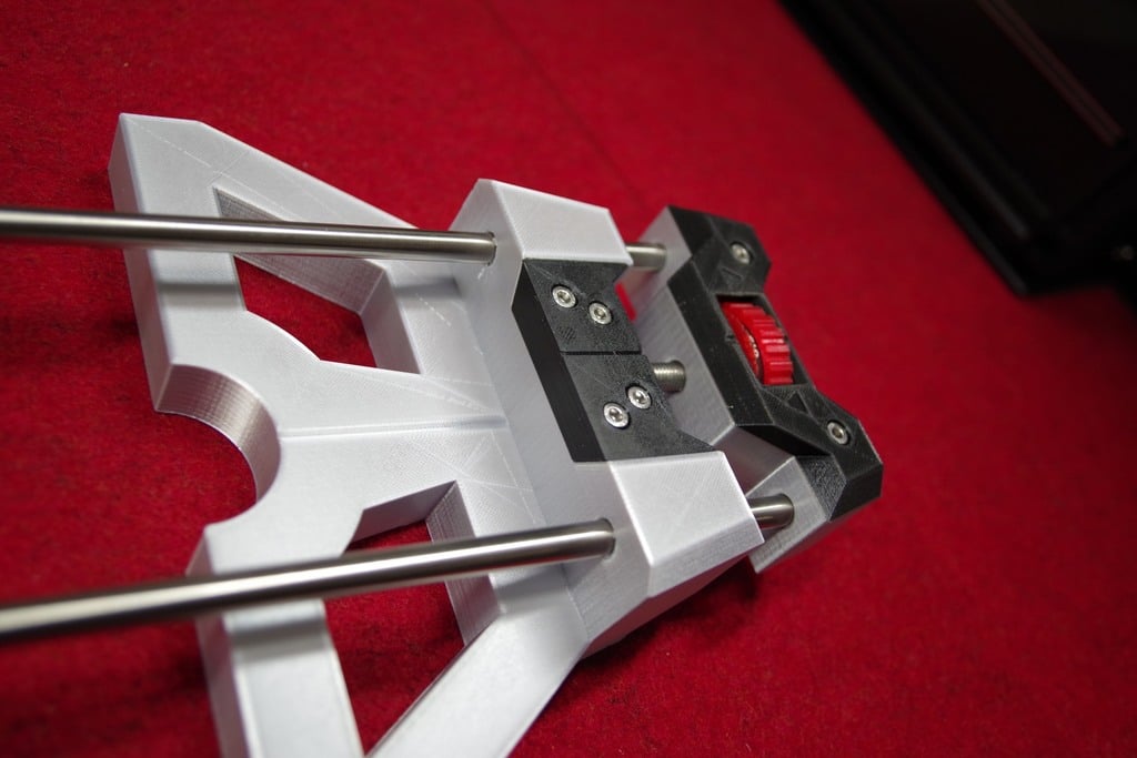
Hi guys! === A few days ago I wanted to print a parallel guide from another Thingiverse user but the result did not work for me (unusual material needed, imprecise rod fittings, …). So I took the challenge and tried to come up with something that fits to my needs. This Parallel Guide is for the Bosch POF 1400 router (or Bosch POF 1200). It might fit to other routers that use 84mm distance between the rods, each rod 8mm in diameter. Main features === * Very sturdy and precise * Precise length adjustment with large wheel and scale on separate wheel (that can be set to zero) * Markers along the center of the guide for alignment (to be used like notch and bed sighter towards work piece) * Rods longer than the original parallel guide for more flexibility Disclaimer === * I used the some material (e.g. screws) available to me – see Material List. Due to tolerances of parts and 3D printing it might need some testing or tweaking on your side. * Material costs about 11 EUR plus 3D printing material * One turn of the adjust wheel equals 1.25mm (and not 1mm) due to standardized size of screw thread. Therefore the measurement label contains 0...1.25mm. Detailed Steps === 1. Print all parts once (see 3D printing hints, print rod caps two times) 2. For the Guiding Part… 2.1. Carefully remove the support structures from printing (especially from screw holes) 2.2. Insert the Carriage Bolt into the Guiding Part – Base. 2.3. Put the Guiding Part – Cap on top 2.4. Fix it using 4x M4 screws and nuts (and don‘t use too much force) 3. For the Adjust Wheel… 3.1. Carefully (!!!) remove the support structure from the Adjust Part (for the Washer) 3.2. Insert the M8 Screw Nut 3.3. Insert the Washers on each side (you might need a hammer for that – make sure they are slightly higher than the printed part, since they are the contact surfaces to the Base) 3.4. Clip on the Measure Part (make sure the settings ring is at the opposite side (Note: I added some masking tape on the shaft of the Adjust Part to make it fit and rotate smoothly) 4. For the Setting Part… 4.1. Check fittings direction of the rods in the Guiding Part (since holes and rods will be slightly non-symmetrical, so you‘ll find a preferred orientation) 4.2. Add a slight slit at the end of the rod to one side (approx. 6.5 … 7.5mm from end of the rod – see below for the reason and size of the slit) 4.3. Check orientation of the slits and insert into the Setting Part – Base (you might need to use a hammer) 4.4. Use the 2 smaller holes in the Base to insert Slim Nails or something like that. These nails will fix the rods tightly if done correctly. (If you have problems to find the slit, then look through the hole against a light source. Then you‘ll see if it is correct. And make sure the nails don‘t stick out of the bottom of the base to avoid injuries.) 4.5. Insert the previously prepared Adjust Wheel. (It will fit tight, but it will rotate. If it is loose, you‘ll have some unwanted backlash when adjusting.) 4.6. Put the Setting Part – Cap onto it (and check the alignment at the sides) 4.7. Fix it using 2x M4 screws and nuts (and don‘t use too much force) 5. You might complete your work adding the Rod Caps to the end of the rods. Material List (additional) === * 2x50cm Rods (stainless steel, 8mm outer diameter, 6mm inner diameter for rod caps) * 1x M8 Screw Nut * 2x M8 Washers (about 20mm outer diameter) * 1x M8x80 Carriage Bolt according DIN603 (80mm is the minimum length being useful) * 6x M4x30 Hex Socket Cap Screws & Screw Nuts according DIN912 (or similar) * 2 Slim Nails (or similar) * Office stuff (a printer for the label, adhesive tape, ...) General === * Start printing the smaller parts that need to fit to the material (e.g. nuts) to check fittings * I used simple PLA * Print in fine resolution (0.1mm) * Print with slight support (only connections from base) * Use Skirt (not brim) * Fit might be very tight (and adapted to the material I had at home) – so check your material * Be patient: in my case it was about 30h printing time (plus all my previous tries :-) Printing Orientation & Color === * Adjust Wheel – Adjust Part: Print with larger part on the heatbed. My color: red * Adjust Wheel – Settings Part: Print with the larger part on the heatbed. My color: red * Guiding Part – Base: Print with the large flat surface on the heatbed. My color: gray * Guiding Part – Cap: Print with the upper side (large screw holes) on the heatbed. My color: black * Setting Part – Base: Print with the upper side (screw holes) on the heatbed. My color: gray * Setting Part – Cap: Print with the larger side (bottom) on the heatbed. My color: black * Rod Cap: The small side (end inside the rod) on the heatbed. My color: red. Adjust Wheel - Measure Part Label === * Print the PDF file using („no resize“) * Cut it carefully * I used standard glue to fix it onto the Measure Part * And, I added some surface protection to the paper by using standard adhesive tape (but it carefully – no overlap is allowed) Have fun & enjoy your woodwork! ===
With this file you will be able to print Parallel Guide for Bosch POF 1400 or 1200 with your 3D printer. Click on the button and save the file on your computer to work, edit or customize your design. You can also find more 3D designs for printers on Parallel Guide for Bosch POF 1400 or 1200.