Parallel Laser Friction Fit Gauges
thingiverse
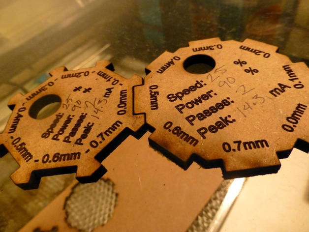
Friction fitting is a difficult process, especially when working across materials that may react differently to the laser. Make these gauges out of your favorite materials to determine how to adjust your parallel cuts to create a tight fit. Cut in increments of 0.1mm. Includes a hook hole and space to log your cut info, so you can recreate exactly the cut you made when fabricating the gauge. Use with my Friction Fit Gauge to get tight finger joins, even between different materials. Instructions Make both gauges, and log the settings. To determine the width of slots, fit the 0.0mm tab on the tab gauge into a slot on the slot gauge. The label on the fitted notch shows how much you should subtract from the width of the notch to get a fitting slot. For example, on a material that fits into the slot labeled -0.2mm, the width of any slot on your project will be 0.2mm less than the width of the corresponding tab. To determine the width of tabs, fit the 0.0mm slot on the slot gauge over a tab on the tab gauge. Add the amount on the fitting tab to your slot width to generate a fitting tab. When cutting your project, use the same cutting settings as the ones you logged on the gauge.
With this file you will be able to print Parallel Laser Friction Fit Gauges with your 3D printer. Click on the button and save the file on your computer to work, edit or customize your design. You can also find more 3D designs for printers on Parallel Laser Friction Fit Gauges.