Park Bike Stand Adapter for Roundish-Tube Trek OCLV Road Frames
thingiverse
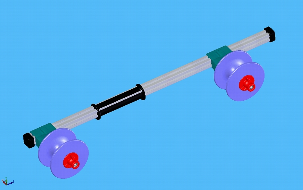
Read through the parts list and description before making one of these. This device is a relatively cheap workaround for a common problem. 1each - 2020 extrusion 60cm long - (Main Rail) 1each - 2020 extrusion 20cm long - ("T-Rail") 10each - M5 2020 t-Nuts (M5 or 10-32) - Slide Locks & "T" Mount 2each - 1/8" x 1.5" wide thick aluminum strip, 2.36" (60mm) long & drilled for M5 bolts 8each - M5 x 10mm hex bolts and flat washers (attaches gusset plates for the "T" mount) 2each - fender washers (Smoother tightening) 2each - 10-32 threaded rod 5.125" long (assembly rods) 2each - 10-32 hex nuts (loose or glued into thumb nut) 3each - 1/4-20 x 3/4" button-head screw (holds end caps) 2each - 3D Printed Park Mt Trolley v2.stl (slide position and lock donuts) 2each - 3D Printed pmount.stl (Donut allows frame tubes up to 1.75" dia.) 3each - 3D Printed pmoutn 2020cap.stl (soften ends of 2020 rail) 2each - 3D Printed park mt nut.stl (tightens trolleys and holds rubber strap) 1each - 3D Park std mt.stl (makes rail round for better Grab) 2each - 3D Printed Hex Nut Lock (glues into knob to retain hex nut) 2each - 1.25" x 10" slice of inner tube punched at 1" intervals (frame hold down) *** NOTE: this project taught me that M5 and 10-32 while different, they are so close in thread pitch that they are interchangeable !!! *** [[ all of the above parts cost me about $35, not including the PLA filament. ]] I bought a Park PRS-6 stand for home use more than 20 years ago when I only owned steel frame road bikes. When I bought some used 1994 through 2004 Trek OCLV bikes after 2014 I found that clamping the alloy seatpost wasn't comfortable for work height. Looking at car bike racks and other options I decided to cook my own solution. Along the way, I realized that even purpose built devices didn't raise the bike high enough since the center of the spring-loaded clamp on the Park Tool PRS-6 is only 41" off the ground. The "T" adapter gives me the same frame height as I would get clamping a steel frame in the middle of the seat tube. If your stand is foot or two taller than my PRS-6, you can skip the T-adapter (and its gusset plates) and just use the round sleeve adapter on the horizontal bar. I found the sliding nature of it great to easily find the balance point of the frame as it slides nicely until the claw (clamp) is closed. This stand adapter is great for gear & brake adjustments as well and headset replacement, but I would do forceful bottom bracket and pedal work on the floor for personal and frame safety. I printed all of these parts in PLA because I still haven't mastered ABS on my consumer-grade printers. To my surprise, the PLA parts work perfectly! The other hack is my use of T-Nuts to provide a slide-lock function. It became obvious real quickly that the T-Nuts bite the aluminum. While the printed "trolleys" slid smoothly the T-Nuts sharpness made them stick in the extrusion channel. The solution was simple, file off four edges on each of the two sliding T-nuts. The other nice thing is that when you loosen the locking knob a turn or two, you can then push on the knob and actually hear the T-Nut unlock itself. I didn't plan this, but I did get lucky. Locking the threaded rod in the T-Nut is what makes this design work !! I threaded in the steel rod so that it comes out the bottom of the T-Nut exposing about 1mm. I then put the rod and T-Nut loosely between the jaws of a vise and used a center punch and hammer to deform the threads and effectively "peen" the rod into the T-Nut so that it will never unscrew or even turn. This make the knob assembly do its job correctly. ( I initially though of using Loctite and then realized that peening made more sense. One of the design challenges in working with 8020 or Bosch style T-Slot-Extrusion as a main element was how to clamp square material in a claw designed for round tubes. The solution was a simple sleeve that made the 20mm by 20mm square material, round. Because I only have FDM printers I needed to build this vertical to keep it smooth and avoid having complicated and hard to remove support structure in the printing. I ended up creating an X or cross-shaped detail in the middle of the sleeve to keep the four sections from deflecting too much. Simplify3D added support under the X/Cross. I also went with a 4mm support pitch and a 25% support fill. After printing it was easy to remove the support. To remove the X/Cross I simply slid the sleeve on a piece of extrusion and it cut out the 0.05" thick X/Cross in a blink with a quick blow from a hammer or a small piece of 2x4 stud. The trolleys were printed with the flat side on the bed and the cone shape facing up. The majority of the support was inside the channel where the 2020 slides. This creates a small problem removing the large amount of support. In particular, the support material that fills the assembly hole makes the removal of fill a real pain. I ignored this on the first print, took the trolley to a vise open to 21mm and used a 1/2" round bar to punch out the support. It removed the support, but also broke the model. Before I removed support from the second trolley I drilled out the majority of the support going through the assembly hole with a large drill bit. After drilling, the removal trick on a vise worked great. The Spools were printed with the large flat side down and large pitch and low fill for the support made its removal very easy. The spools are designed for carbon fiber tubing/shapes that is less than 1.25" wide (or diameter). Also, the support makes for a rough finish where the frame comes to rest. I've solved this by using red shop towels or strips of inner tubes to keep from scratching a top tube. I also installed a wrap of Cinelli cork bar tape on the hub of the spool and held it in place with a few wraps of electrical tape. This cork bar tape made the center of the spool soft and nicer to the frame. The end caps and the knobs printed without any support or any problems. I used a 50% fill setting, 4-inner/outer-shells, and 0.24mm layer thickness for all parts. I created nut-lock tubes to hold the hex nut in each knob and an add-on or alternative to gluing in the hex nut. I made them and show them in the design, but never used them in my working device. I went with 5-minute JB-Weld and painted the outer edges of the nut and interior of the knob where the nut comes to rest. I then put a threaded rod up through the bottom of the knob and used it to install (pull down) the hex nut before the JB-Weld set up. My rubber straps came from a mountain bike inner tube that I cut into 1.25" wide by 12" long strips and then used some cheap Harbor Freight punches to create the hole pattern. The head of the knob works great as a post for these improvised straps. You will need to drill and tap 2020 rod ends to install the end caps. I used 1/4-20tpi button head screws.
With this file you will be able to print Park Bike Stand Adapter for Roundish-Tube Trek OCLV Road Frames with your 3D printer. Click on the button and save the file on your computer to work, edit or customize your design. You can also find more 3D designs for printers on Park Bike Stand Adapter for Roundish-Tube Trek OCLV Road Frames.