PCB cutting guide (customizable)
thingiverse
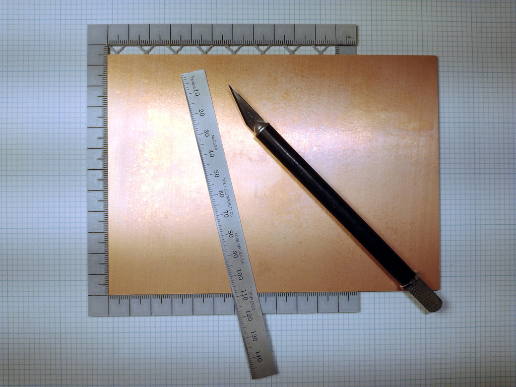
This is a cutting guide designed for use with printed circuit boards. It can also be used for accurate marking of other sheet material. Several sample STL files are provided but this script is really intended to be customized to your needs. Main features: * Metric, decimal inch, or fractional inch rulers * Arbitrary width and depth * Solid or open-grid base * Rulers are flush with board top by default * Any or all edges can be open (ruler flush with base) to handle over-size boards * Rulers can be numbered or plain * Most dimensions are customizable With this guide one can achieve extremely accurate cuts. Using the guide and tools in the first photo I was able to cut the board shown into two equal-sized pieces with an accuracy of better than 0.01 mm (the resolution limit of my calipers). # Usage tips Mark one corner of your circuit board with ink. Align this corner with one of the guide's corners and perform all measurements from there. This compensates for any variations in the board's edge and thus helps ensure accuracy when cutting the board. For cutting circuit boards I find it's best to mostly use the sharp side of the blade to cut through the copper cladding. Once you reach the fiberglass switch to using mostly the back side of the blade tip to scrape away the material. Cut on both faces of the board, alternating sides occasionally, and meet in the middle. While cutting periodically check the alignment of the two cuts and adjust the cutting angle as needed. Go slowly; it usually takes maybe 100 strokes to cut through a 1.6 mm board. For fine-tuning measurements one can place a shim between the circuit board and the inner ruler edge. X-acto #11 blades are 0.51 mm thick and work well for this (take care not to cut yourself while scribing the board). One user (griffinmt) suggested gluing 220 grit sandpaper to the back of the guide to keep it from slipping while cutting. # Printing tips ### Material choice Prints should ideally be done in a dimensionally-stable material such as PETG. If mixing materials from layer to layer note that PLA and PETG won't adhere to one-another. ### Compensating for shrinkage Some materials, such as PLA, may exhibit shrinkage once they've cooled. If you encounter this then the following should help: * Enable "`Shrink compensation`" * Measure the printed length of the long side ruler and enter this value for "`Measured length of long-side ruler`" * Measure the printed length of the short side ruler and enter this value for "`Measured length of short-side ruler`" When printed the shrinkage should be compensated for and the rulers should be accurate. When measuring the printed parts measure from the first tick to the last tick (ignore any blank space in the corners). If the long side hasn't shrunk then the values for "`Measured length of long-side ruler`" and "`Board width`" should be the same. Likewise if the short side hasn't shrunk the values for "`Measured length of short-side ruler`" and "`Board length`" should be the same. Note that the printed guide may shrink by a different amount in each direction. I suspect that guides printed with an open grid base are less prone to shrinkage than those having a solid one. ### Marking visibility To make the markings more visible one can change to a contrasting filament color for the single layers below the groove bottoms. Ironing the visible portions of those layers is recommended (quick way: enable ironing for all top surfaces). Ironing the tops of rulers may require manual clean-up of the grooves. If you're able to print using multiple filaments you can use the "no markings" (for an unadorned guide) or "fill markings" (for just the grooves) options for the `output` setting to aid in filling in the markings with a contrasting color. ### Creating a flat guide To create a flat guide one can do either of the following: * Set the board thickness (`t`) to 0.0 and select no open sides This results in non-overlapping rulers (corners are blank) * Select both sides open for both the long and short sides This results in overlapping rulers at the corners # Options This is a summary of the available options, broken down by section. All dimensions are in mm unless otherwise indicated. --- ### General settings * `$fn` → Number of segments in a circle This only affects corner cut-outs. * `output` → Desired output Most of the time one should choose `normal`. If you want to print in multiple colors you may find the `no markings` or `marking fill` options useful. Note that `marking fill` preview may be incorrect or fail entirely; the rendered output is correct though (albeit with possibly a few zero-width shapes). * `units` → Sets the units used for the rulers and solid base grid: * `mm` → Ticks every 1 mm, numbers every 1 cm * `decimal inch` → Ticks every 1/10" (dots every 1/20"), numbers every 1 inch * `fractional inch` → Ticks every 1/32", numbers every 1 inch The chosen units are used for display purposes and also apply to values entered for the board width (`w_`), board length (`d_`), and solid base grid spacing (`egs_`) settings. Those three settings take values in either mm or inches, as appropriate. The following options control the basic size of the guide. These dimensions exclude any raised rulers around the edge. * `w_` → Board width (long side) in ruler units * `d_` → Board length (short side) in ruler units * `t` → Board thickness (typically 1.6 or 0.8 for PCBs) * `b` → Base thickness * `es` → Edge (ruler) width or length (on each side) This applies only to sides that are not open. To control the edge width for open sides see `open_s` below. The following two options set the depth of all inscriptions (text and lines) and the width of non-text lines (text line width is controlled by the chosen font). * `gw` → Groove width * `gd` → Groove depth --- ### Rulers These control the appearance of the rulers around the guide's edges. The following option controls set the tick orientation of base-level rulers (ones along open sides): * `base_ruler` → Base-level ruler tick orientation: * `pointing out` → Ticks touch the ruler's inner edge, numbers are near outer edge * `pointing in` → Ticks touch the ruler's outer edge, numbers are near inner edge This option only affects the orientation of base-level rulers; the raised rulers always have their ticks pointing out. * `extend_ticks_to_base` → Extend ticks down to base on ruler inner edges? Enabling this option can make it easier to accurately mark lines especially when the item being marked is thinner than the guide (e.g. a 0.8 mm circuit board on a 1.6 mm guide). The downside is that the inner edges won't be smooth lines; this may affect the guide's accuracy. **Numbering** Rulers can optionally be numbered. * `ruler_numbers` → Enable to add numbers to rulers The following set the font and size used. For a list of fonts available on your system look in OpenSCAD's **Help → Font List** menu. * `number_font` → Font for numbers * `number_size` → Font size for numbers The numbers on each ruler can be positioned either aligned with the tick they reference or be located to the side of the tick: * `long_number_align` → Number alignment for long side * `short_number_align` → Number alignment for short side In addition, the short-side numbers can optionally be rotated by 90° in either direction: * `rotate_short_numbers` → Rotate short-side numbers Number positions can be tweaked with the following: * `number_edge_offset` → Distance from numbers to ruler's non-tick edge * `long_number_h_offset` → Distance to shift long-side text left or right * `short_number_v_offset` → Distance to shift short-side text up or down The following can be used to keep the major ticks from passing through the numbers: * `major_tick_reduction` → Length to reduce major ticks by The code makes no attempt to prevent numbers from being partially displayed. Instead, the following options can be used to hide the first or last digit of any of the rulers: * `long_lower_suppress_first_number` → Suppress the first number on the long-side lower ruler * `long_lower_suppress_last_number` → Suppress the last number on the long-side lower ruler * `long_upper_suppress_first_number` → Suppress the first number on the long-side upper ruler * `long_upper_suppress_last_number` → Suppress the last number on the long-side upper ruler * `short_left_suppress_first_number` → Suppress the first number on the short-side left ruler * `short_left_suppress_last_number` → Suppress the last number on the short-side left ruler * `short_right_suppress_first_number` → Suppress the first number on the short-side right ruler * `short_right_suppress_last_number` → Suppress the last number on the short-side right ruler --- ### Base The base forms the central portion of the guide. It can either be an open diamond grid or a solid flat surface. In the latter case grid lines can be inscribed upon it. I suspect (but have not experimentally verified) that an open base is less susceptible to shrinkage than a solid one. Using an open base also results in a much quicker print time (on FDM printers) without impacting usability. * `open_or_solid` → Solid base or open grid base? * `solid_grid` → Etch grid into solid base? * `egs_` → Etched grid spacing in ruler units (see `units`, above) * `gs` → Grid spacing (for open base) in mm * `gt` → Grid line width (for open base) in mm --- ### Corner cutouts To make in easier to tightly abut the circuit board to the guide edges one can optionally cut away a small portion of the inner corners of raised rulers. * `corner_cutouts` → Include corner cutouts? * `corner_cutout_radius` → Corner cutout radius --- ### Open sides Any or all of the guide's sides can be open. An open side does not have a raised ruler. Instead the ruler is placed within the central portion of the guide at base level. The following options control which sides are open: * `long_open` → The long sides that are open * `short_open` → The short sides that are open Rulers on open sides are placed on a solid surface at base level. The following controls this surface's size: * `open_s` → Open side width or length (perpendicular to outer edge) Note that this value is in mm. For a metric guide 10 mm is a sensible choice. For an imperial guide you may prefer to use something like 12.7 mm (½ inch). --- ### Preview options A circuit board, sized to fill the maximal usable area, can optionally be displayed. This can make the design easier to visualize while you select options. The circuit board is not included in the final render. * `show_board` → Show circuit board? * `transparent_board` → Transparent circuit board? --- ### Shrink compensation As mentioned above, some materials (PLA in particular) are susceptible to shrinkage once the print cools. The options in this section can help fix that issue. See **Compensating for shrinkage** in the **Printing tips** section above for usage. * `shrink_compensation` → Shrink compensation? * `measured_long` → Measured length of long-side ruler * `measured_short` → Measured length of short-side ruler
With this file you will be able to print PCB cutting guide (customizable) with your 3D printer. Click on the button and save the file on your computer to work, edit or customize your design. You can also find more 3D designs for printers on PCB cutting guide (customizable).