PCB (UV) Lightbox
thingiverse
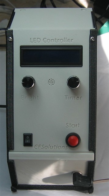
Light controller box designed for exposure to photosensitive circuit board This is a remake of ThechBuilder PCB exposure box and the EleLab systems base module. This project consist of 3 parts: - The Controller in EleLab style; - The PCB print and code; - The Led light box. The Control Housing. The EleLab 100mm base frame is adapted so the Bottom can hold now a modular build plate system for whatever you need, in this case a Mean Well RS-25-12 (100-240V to 12VDC 2Amp) power unit. And added two rails in the frame for expansion floors. It is possible to use the original EleLab frame STL if you don’t use the in-module power supply or use it as an add-on for the EleLab system. The STL files: UV Frame 100mm (adapted or original) UV Power supply inlay tray (only fit the adapted frame) UV Top UV Lower UV Front All is printed with 0.3mm layer to speed up printing time. Filament used PETG for frame and PLA for all others. The Front panel needs support on the lower lip because it is printed front face down. If you want the text colored, change color after the second layer and finish with that color or change it again after three layers. The Controller PCB. The ThechBuilder LED controller is adapted and the PCB is redesigned for milling (by a Stepcraft CNC-milling machine). Therefore the spurs are a bit thicker than needed but this is because the PCB is not etched but milled. On the print I placed 2 rows of 15 Female Headers for the Nano (easy to tear of the Nano for reuse, optional). For the buzzer I used a JST XH 2p connector just because I had one left. All other wires are soldered on the print. Tools used for PCB milling: Outline spurs: V-bit 45°, 2mm Cut diameter, 3.17mm ax, cutting depth 0.1mm, feedrate 1200 mm/min Pocketing print: V-bit 90°, 3mm Cut diameter, 3.17mm ax, cutting depth 0.1mm, feedrate 1200 mm/min Drill: 0.9mm for all except for the 2 screw terminals these need 1mm holes Cutting: Endmill 1mm, 3,17 ax, cutting depth 1mm, feedrate 600 mm/min, two passes. Approximate running time 48 mins. The Led light box. The lightbox is made from a storage box size 30x17x15 cm but any box with a lid can do the job. Cut out a window in one side for placing the PCB to be exposed. On the inside of the lid glue a piece of cardboard or plywood build plate to hold the Leds. Cut the led strip into strips (on this box 15 leds per section) and place the pieces next to each other on the build plate make sure the positive points are all the same side placed. Now soldering all the positive points to a wire on one side and do the same with the negative on the other side. Electronics needed: Optional 12 VDC 2 Amp Power unit (Mean Well RS-25-12) or any 12V 2 Amp power (from power rail or DC jack or direct to print) 16-2 LCD display Optional Active Buzzer 5V 2x 10k Pot meter linear + Knobs Push button (reset-type standard open) On-Off (Flip) switch Optional DC-Jack for 12V out to Leds Electronics on PCB: Arduino Nano v3 or compatible clone TIP31C (NPN transistor) 10k Trim pot (Cermet type 3362) Res 100 Ohm Res 220 Ohm Res 470 Ohm Res 10k Ohm 2x Screw terminal 2 pin optional male/female headers alternative for soldering wires. Electronics for Ledbox: UV led strip 5mtr 12V Optional DC jack for power supply Hardware general: 8x M3-5mm screw (secure display and PCB) 4x M2 or 2.5 to secure the front and lid This is still working in progress, espescially de arduino code could be better.
With this file you will be able to print PCB (UV) Lightbox with your 3D printer. Click on the button and save the file on your computer to work, edit or customize your design. You can also find more 3D designs for printers on PCB (UV) Lightbox .