Peg-Perego tractor battery upgrade using Snow Joe iBAT40/iBAT40XRP V 2.1
prusaprinters
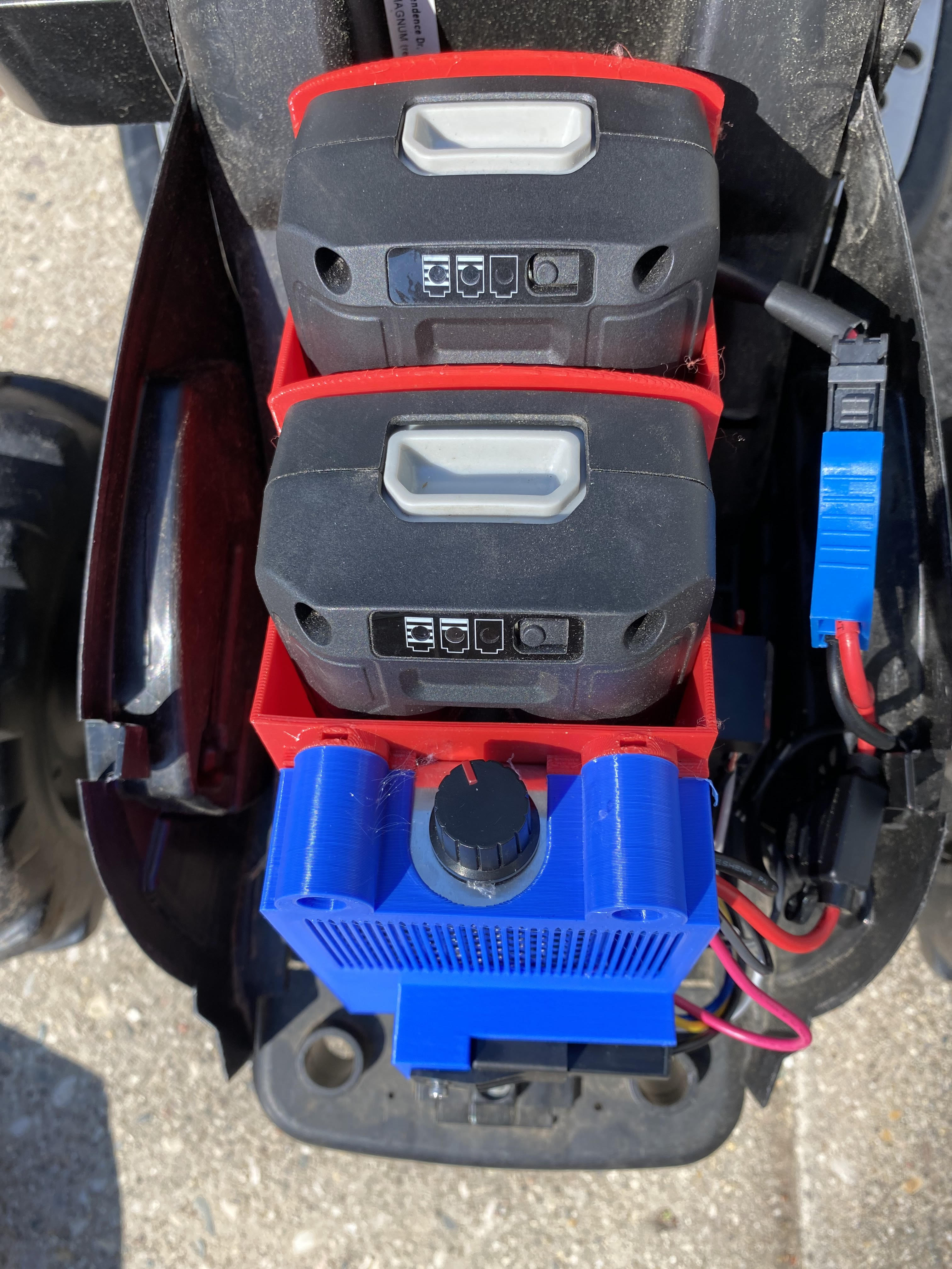
<p>Edit: This is still a work in progress. V2 is uploaded. The electronics cover is a bit of a cobbled-together mess. There's certainly a better design that will minimize supports and maximize quality. I will need to do a rebuilt to find it, though. This version is functional, if nothing else.</p><p>Description continues:</p><p>I got tired of losing the proprietary charger for my kid's ride-on tractor. Plus, it always seemed to run out of juice right after the kids got all amped up to ride. Nothing puts a damper on fun like having to wait 3-5 hours for the battery to charge. Meanwhile, I have four 40v batteries hanging around my garage that I use for the three months out of the year that we get snow. It's a perfect resource. After a LOT of reading . . . I'm still not confident that I know what I'm doing, but that damn thing seems to run. </p><p>That said, you're dealing with 40v. I was not the happiest as I tested the fit of the terminals and used a meter to test the exposed ends of the terminals to make sure they were making contact inside the battery. Plus, if you don't dial your speed controller right, you can burn out your motors. Not to mention the fact that you are putting 6 amps of li-ion power six inches in front of your four-year-old. I am not an expert. Use this design at your own risk.</p><p> </p><p>Now onto the fun:</p><p>First, the BILL OF MATERIALS:</p><ul><li>Speed controller - the heart of the operation. This steps down the 40v to something close to 12 volts that the motors can handle without burning out. I hear a slight adjustment above 12v will get you a little extra speed without damaging the motor as well. <a href="https://www.amazon.com/gp/product/B071NQ5G71/ref=ppx_yo_dt_b_asin_title_o01_s00?ie=UTF8&psc=1">https://www.amazon.com/gp/product/B071NQ5G71/ref=ppx_yo_dt_b_asin_title_o01_s00?ie=UTF8&psc=1</a></li><li>Peg-Perego wiring harness with built-in fuse - this is what makes the system revertible. <a href="https://www.amazon.com/gp/product/B08KJQ7X1P/ref=ppx_yo_dt_b_asin_title_o06_s00?ie=UTF8&psc=1">https://www.amazon.com/gp/product/B08KJQ7X1P/ref=ppx_yo_dt_b_asin_title_o06_s00?ie=UTF8&psc=</a>1</li><li>Battery connector - I'm most proud of this find. It's a dead ringer for the terminals used by the Snow-Joe 40v batteries. Plus, they are super cheap and I wasn't charged shipping. I recommend you buy at least 10. They are cheap enough to warrant buying extras and with the tight fit in the print, there's a chance of damaging them while inserting, though I have found them to be surprisingly resilient. <a href="https://www.te.com/usa-en/product-60701-1.html?te_bu=Cor&te_type=email&te_campaign=oth_usa_cor-oth-usa-email-ecomm-fy19-hbrs-oconf-prdlink_sma-716_2&elqCampaignId=37418">https://www.te.com/usa-en/product-60701-1.html?te_bu=Cor&te_type=email&te_campaign=oth_usa_cor-oth-usa-email-ecomm-fy19-hbrs-oconf-prdlink_sma-716_2&elqCampaignId=37418</a></li><li>Over-Discharge Protection module - Lithium-Ion is sensitive to discharging and if you go too far, your battery will brick. This module activates a relay to shut down the connection if the voltage drops below a certain value. The connection is restored once the voltage returns to a usable level. <a href="https://www.amazon.com/gp/product/B08FRB17C7/ref=ppx_yo_dt_b_asin_title_o07_s00?ie=UTF8&psc=1">https://www.amazon.com/gp/product/B08FRB17C7/ref=ppx_yo_dt_b_asin_title_o07_s00?ie=UTF8&psc=1</a></li><li>48v relay - this is the actual switch, triggered by the Over-discharge module. <a href="https://www.amazon.com/gp/product/B07QRPFT96/ref=ppx_yo_dt_b_asin_title_o02_s00?ie=UTF8&psc=1">https://www.amazon.com/gp/product/B07QRPFT96/ref=ppx_yo_dt_b_asin_title_o02_s00?ie=UTF8&psc=1</a> CAUTION: I fried two fuses before realizing that the wire colors were meaningless. I ended up using the picture here to identify the pin numbers based on their position POSITION. Ignore the colors. <a href="https://www.mictuning.com/u_file/1610/products/19/07a6902dde.jpg">https://www.mictuning.com/u_file/1610/products/19/07a6902dde.jpg</a></li></ul><p>Optional</p><ul><li>Fuse holder and fuses - I'm not sure this was strictly necessary but I wanted to put a fuse between the hot terminal on the battery and the speed controller just in case something shorts in that system. Better safe than sorry <a href="https://www.amazon.com/gp/product/B088FNTJDV/ref=ppx_yo_dt_b_asin_title_o02_s00?ie=UTF8&psc=1">https://www.amazon.com/gp/product/B088FNTJDV/ref=ppx_yo_dt_b_asin_title_o02_s00?ie=UTF8&psc=1</a></li><li>Spade connectors - to make connections easy, I picked up a box of spade connectors. <a href="https://www.amazon.com/gp/product/B07RT4RSGJ/ref=ppx_yo_dt_b_asin_title_o01_s00?ie=UTF8&psc=1">https://www.amazon.com/gp/product/B07RT4RSGJ/ref=ppx_yo_dt_b_asin_title_o01_s00?ie=UTF8&psc=1</a></li><li>4 Position Terminal Block - wire nuts work just as well but this makes for a slightly more organized wiring setup. https://www.amazon.com/gp/product/B0744CYJJ7/ref=ppx_yo_dt_b_asin_title_o00_s00?ie=UTF8&psc=1</li><li>You will also need some appropriate wire. The Peg-Perego harness uses 12ga. I used the same for the rest of the system on mine.</li></ul><p>Total cost of this project using the required materials is less than $70 not including the print. The individual cost of these components is much lower if you buy them in multipacks. I've found that many of these components can be purchased in packs of three for about 25% more than the singles.</p><p>The print takes the place of the current battery holder. It reuses the same screws that hold down the battery bracket on the original design. This upgrade is fully revertible. No permanent modifications have been made to the original design!</p><p>ASSEMBLY</p><ol><li>The battery connectors slot into the bottom of the new holder. They are intentionally a tight fit and “should” snap into place preventing removal.</li><li>These connectors are then wired in SERIES. If you don't know what this means, this is not the project for you.</li><li>The fuse between the battery and speed controller should go on the front hot terminal(this should be the “passenger” side of the vehicle). Attach a regular piece of wire to the front negative terminal. I used solder on all the connections between the terminals and wiring just to make sure there was good contact.</li><li>These wires are then split. The hot side connects to the positive input terminal on the over-charge module and connection 30 on the relay. The negative side connects to the negative input side of the over-charge connector and to the negative input side of the speed controller.</li><li>The output side of the over-charge module then connects to the control side of the relay: positive to connection 85 and negative to connection 86.</li><li>Terminal 87 connects to the positive input side of the speed controller.</li><li>The wiring harness is then connected to the output side of the speed controller.</li><li>Then, screw the whole assembly down using the old screws in the old mounts on the tractor frame and connect the harness.</li><li>Adjust the cutout and reconnect voltages. Instructions for programming this can be found on the product page and it's very simple. I'm still in the testing phase but as of now I am disconnecting at 36 volts and reconnecting at 39 volts (read as “3” on the module).</li><li>You will then need to set the speed controller to the right voltage. The speed controller only functions under load so simply attaching a meter to the harness will show you 40v no matter where you set the dial. I connected the old battery, propped the rear up, and hit the gas to gauge the speed of the wheels. I then connected the new setup, turned the speed control knob all the way counter-clockwise, and briefly hit the gas. On my system, counter-clockwise reduced the voltage. Your mileage may vary. Once that was ascertained, I turned the speed control all the way down, held the gas, and slowly increased the voltage until the wheels were spinning at about the same speed as the original battery (with maybe just a hair more)</li><li>Once the over-charge module and speed controller are programmed, you can then install the electronics cover.</li></ol><p>FINAL NOTES:</p><p>I ran a dozen or so different test prints to get the fit on the battery, the contacts, and the chassis just right. Once that was settled, the print took 19 hours and an hour of assembly was all it took before my kid was off to the races. I'm super annoyed that nobody had done this before but hopefully this will prevent my frustration from becoming yours. Hit me up with any comments or feedback. An ambitious maker may be able to squeeze an extra battery into this setup. And please don't blow up yourself or your kid.</p><p>Prior versions:</p><ul><li>V1.0 - Battery holder and basic wiring. Speed controller taped to front of assembly. Direct wire to speed control and motor. Problems: High risk of over-discharge, unattractive design.</li><li>V2.0 - Disconnect added. Electronics cover added. Problems: forgot to include relay, non-functional design, risk of overheating on speed control due to closed design cover.</li><li>V2.1 - Added relay and holder on electronics cover. Added vent to electronics cover over speed controller. Functional design with battery protection. Problems: electronics cover requires supports adding to print time.</li></ul><p> </p>
With this file you will be able to print Peg-Perego tractor battery upgrade using Snow Joe iBAT40/iBAT40XRP V 2.1 with your 3D printer. Click on the button and save the file on your computer to work, edit or customize your design. You can also find more 3D designs for printers on Peg-Perego tractor battery upgrade using Snow Joe iBAT40/iBAT40XRP V 2.1.