Pegboard Locking Pin, cool design, HELP NEEDED
thingiverse
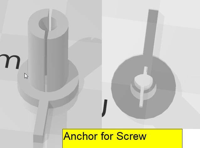
Pegboard Clips Pins Rivets Remix To all, this is a WORK in PROGRESS. There are several other projects out there that have done pegboard pins, rivets, clips, etc, and I would like to thank all of them for their projects, mine is built on theirs. AND, to anyone who is good with OpenSCAD, if you can help ME improve this, to make a parametric version, it is appreciated. I use Sketchup, and I am able to scale these as needed, but an OpenSCAD file would work better. PROBLEM – all the current Clips/Pins/Rivets are essentially a single diameter. BUT, if you check out pegboards, almost ALL the holes are different sizes. They are usually on 1 inch spacing, but the diameters are all over the place. I have 5 different pegboards I work on, and ALL them are of different diameter holes. Tool #1 – I have created a set of spacers, ranging from 5.4 mm dia, to 7.0 mm dia, in 0.2 mm increments. This allows me to figure out exactly what pin diameter is needed, for specific pegboard. Pin #1 – a multi-step pegboard pin, with OUTER diameter of the pegboard hole size, and inner stepped diameter ending up at about 1.25 mm diameter. This inner step, which is the distal 5 mm length of the pin, allows insertion of 1.75 mm printing filament, to lock the pin. The pin itself is split with a .75 mm horizontal slice, so the pin can expand when the filament is inserted. The DIFFERENCE of my pins, versus the others designed, is that I make it the exact diameter of the pegboard hole, there is no EXTERNAL step-up in diameter. Because it fits exactly, it does not take much distal expansion, with the filament, to lock it into place. Now, the downside is that you have to make the pins custom to your pegboard, but once you have it measured, then you are set. Pin #2. A multi-step pegboard pin, as above, outer diameter of the pegboard hole size. An inner stepped diameter, with last 5 mm length being 3 mm inner diameter (again with horizontal slice), and this allows insertion of a #6 sheet metal screw, which expands the end and locks it into place. This is essentially like a wall anchor, but is custom fit for your pegboard, and you can screw things onto the pegboard easily, and also easily remove them There are advantages and disadvantages to both types of pins above, work with them, see what works for you. I have included pictures of what the pin looks like, from the sketchup design. I have also shown a cross-view of it inserted into a pegboard, and how it expands. Now, what I would like to do is make an OpenSCAD file that can create both of these pins. It would essentially be about 3 concentric cylinders, a cross section horizontal section removed, and a base washer 2mm high and 10 mm dia, with NO horizontal slit in it. (see images). If anyone can help, let me know. Otherwise, here are the sketchup files, and images, feel free to use these for PERSONAL use, same as all the other previous individuals’ projects, and again, thanks to all of them, I could not have don’t this without all their ideas. NOTE – this project is built upon all the others who have created pegboard pins, and I will link those later. Right now, I just would like to get some help to make this into SCAD, which could then allow customization of the outer diameter, to fit anyone’s pegboards. thanks
With this file you will be able to print Pegboard Locking Pin, cool design, HELP NEEDED with your 3D printer. Click on the button and save the file on your computer to work, edit or customize your design. You can also find more 3D designs for printers on Pegboard Locking Pin, cool design, HELP NEEDED.