Pendulum Clock
prusaprinters
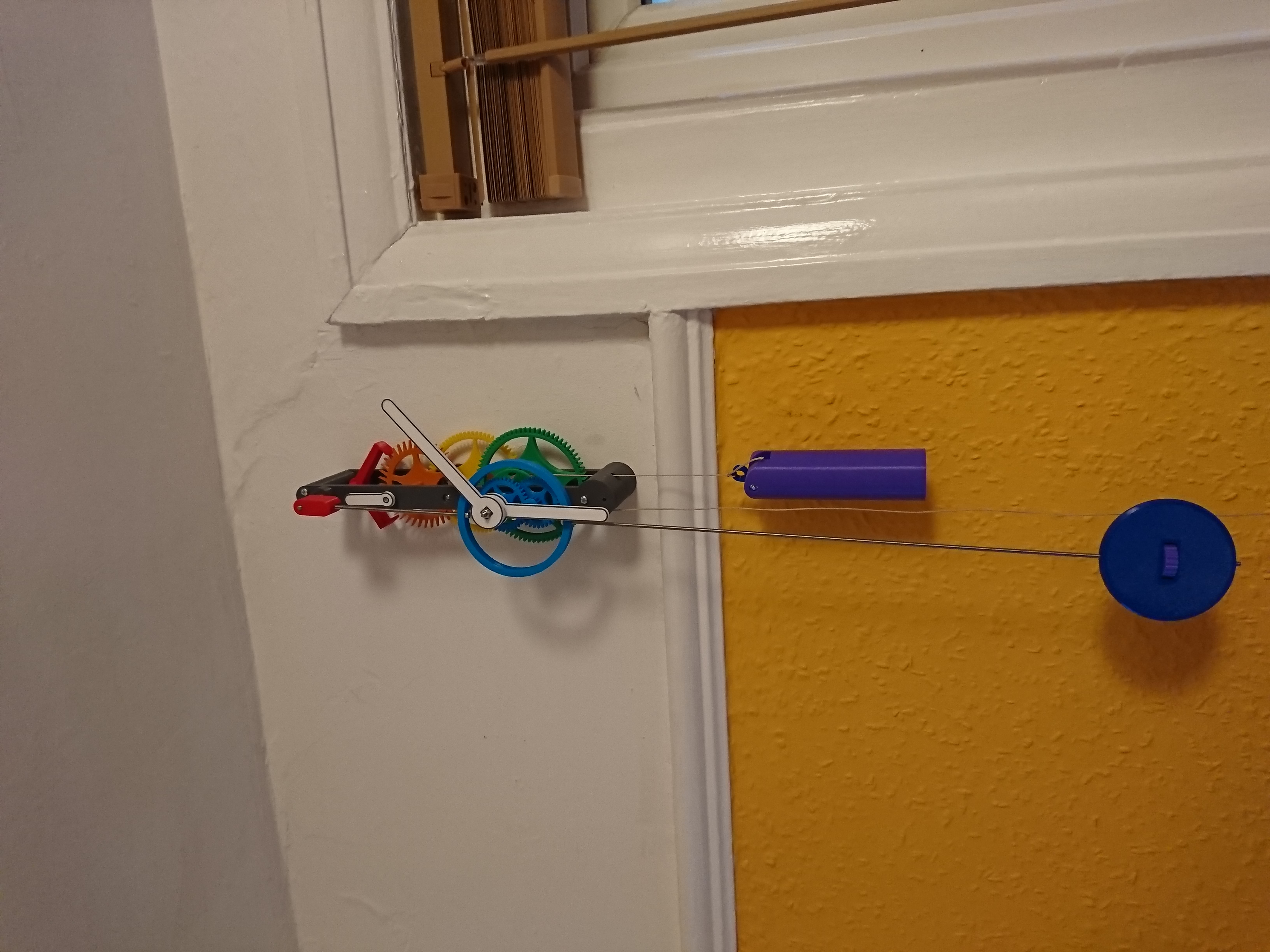
<p>A simple one day pendulum clock, with seconds complication. The clock is driven by a weight on a cord, with a second cord that winds up as the weight winds down. The second cord can be pulled to quickly wind the weight back up. The hands can be set simply by turning the minute hand.</p><p>The weight drops at a rate of about 7cm an hour, so you need at least 180cm of drop for the clock to run for a full day.</p><p>See this video for it in action: </p><figure class="media"><oembed url="https://www.youtube.com/watch?v=4dKu5Yc78iA"></oembed></figure><p>This was printed in PETG, my experience is that PLA warps under stress, so I don't think it will be up to the job. I don't think the printed ratchet mechanism would work with PLA either.</p><p>I don't know what the long-term life of the clock will be - the longest I've had a prototype running is only a month so far!</p><p>Ball bearings are used to reduce friction, so it can run reliably with a weight of only about 300g.</p><p>This needs the following non printed parts:</p><ul><li>8 ball bearings: 3mm internal diameter, 10mm external diameter, 4mm thick</li><li>M3 Threaded rod, 1metre is more than enough</li><li>M3 nyloc nuts</li><li>M3 nuts</li><li>30mm M3 machine screws (x8)</li><li>8mm M3 machine screws (x2)</li><li>M3 spring washer</li><li>1mm diameter clock cord (I think any strong, not-too-stretchy string will work)</li><li>Steel shot (or something similar to fill the weight and bob)</li></ul><p>And the following tools will be useful:</p><ul><li>Screwdriver</li><li>Small bench clamp</li><li>Finger files</li><li>Hacksaw</li><li>Larger file</li></ul><h4>Slicing</h4><p>It is vital to get the slicing right for the gears, as any extra friction introduced from printing artefacts will severely impact the reliability of the clock. I used seam painting for the gears to ensure that seams do not start on the teeth, springs or pallets of the anchor.</p><p>Nearly everything needs to be strong, so I sliced with 3 perimeters, 6 bottom and top layers and 40% gyroid infill.</p><p>PETG strings really quite a lot. This is exacerbated by any small bits of perimeter that can occur. I had to disable Gap Fill for the gears and then tweak the extrusion width for the pinion on gear 1. See gears.3mf and the slicing screenshots. If I didn't do this then I didn't get a clean surface on the gear teeth, which meant a much heavier weight was required to overcome this friction.</p><p>The STL files are almost all in the correct orientation for printing. The lids for the pendulum bob and weight will need rotating so the larger side is on the bottom.</p><p>The bottom plate is designed to have print-in-place nuts inside the pillars. I found that using “Change Colour” rather than “Pause Print” works best, as it keeps the nozzle heated and does a mini-purge afterwards, so you don't end up with a gap in the print.</p><h4>Multi-Colour on a non Multi-Material Printer</h4><p>This is surprisingly easy to do and looks great when printed on a textured sheet. See my write-up on this print: <a href="https://www.prusaprinters.org/prints/150478-multi-material-road-signs-uk">https://www.prusaprinters.org/prints/150478-multi-material-road-signs-uk</a> </p><p>The short version is to tell the slicer that the printer has multiple heads and the M600 command is the gcode needed to switch between heads.</p><p>This is used for the info on the back of the clock plate (optional, it will print fine if you just print the main back plate without it) and the hands (really helps them stand out, worth doing).</p><h4>Post Processing</h4><p>I used a finger file to clean up any imperfects or stringing in the gear teeth. If sliced correctly, there isn't much to clean up. However it's worth manually inspecting every single tooth and filing off any lumps or strings.</p><h4>Assembly</h4><p>Start by putting the bearings into the plates and assembling the gears on the arbours, then put the plates together. Once the arbours and plates are assembled, thread the cords through the bottom plate. Then you can attach the hands and pendulum fixing.</p><p>Assembling the gears together in the plates takes a little trial and error to get everything in the right order. You need to put the gears in in the right order so they can fit together. Have a close look at the photos and assembled model (wall_clock_07.stl).</p><h5>Plates</h5><p>The bearings are hard to push into place, this is where the bench clamp comes in useful to push them flush into the plates.</p><p>The front plate needs a 30mm M3 screw to hold the motion works (the bit that the hands attach to). Push a nut into the front of the front plate (find the hex hole) and then screw the screw in from the back of the front plate.</p><h5>Gears</h5><p>An arbour is an assembled wheel and pinion on a rod. They start from zero (the wheel with the weight) and go up to 3 (the anchor). If there is a bottom_extension to the arbour, it is threaded on the rod under the gear. There needs to be a bit less than 6mm of empty rod to slot into the bottom plate bearing. Too much empty rod and it will poke through the back and into the wall!</p><p>Screwing some of the smaller arbour extensions on to the rod is fiddly. If you struggle, I recommend using a camp and screwdriver to screw an M3 screw into them multiple times before trying again. These extensions are just to hold the gears in the right position.</p><p>Cutting threaded rod is easy with a hacksaw, just make sure to use a file to clean up the ends afterwards.</p><p>Arbour 0 (which has the cord wheel and hands) needs to be 11cm long</p><p>Arbour 1 (second wheel) 6cm</p><p>Arbour 2 (escape wheel) 7cm - so it sticks out the front and the second hand can be threaded on later</p><p>Arbour 3 (anchor) 10cm - so it sticks out the front far enough to hold the pendulum.</p><p>Note - friction between the main gear on arbour 0 and the threaded rod is needed to reliably turn the hands, and not turn the rod when setting the hands. Sometimes I've been able to screw this gear on and it's been very tight, other times I found a drop of superglue on the rod when screwing the gear onto the rod was needed.</p><h5>Cord Wheel</h5><p>There are two cords - one ended in the weight_hook for holding the weight, and one ending in weight_ring to wind the clock back up.</p><p>This is on the same rod as gear 0. It is made of four parts held together with two 30mm M3 screws and two nuts. The cordwheel_click is on the bottom, then the cordwheel_cap, then cordwheel_bottom_segment then cordwheel_top_segment on top. Push the nuts into the holes in the top segment, and screw the screws in from the bottom. The screws should engage with the nuts and pull them down into the top segment a bit. Tie a chord into each segment. I hang the weight from the segment nearest the back of the clock. The weight will hang from the right hand side of the clock.</p><p>The whole of the cord wheel assembly then slots onto arbour 0. The ratchet should satisfyingly click when rotated if this is done right.</p><p>Before assembling the plates, make sure that one cord is nearly fully found up and the other is nearly empty.</p><p>If you are having problems with reliability, try putting a washer on the rod in front of the cord wheel - if the cord wheel was coming into contact with the front plate, this can add too much friction.</p><h5>Hands</h5><p>The hands are held onto the rod loosely. This is so you can turn the hands independently of the rest of the mechanism. Thread either a nyloc nut, or two nuts locked against each other, as far down the rod towards the top plate as you can. Then slot on the spring washer - this is what provides the friction to turn the hands, while still allowing you to set the time.</p><p>Then you can slot the motion works onto arbour 0's rod and the screw in the front plate. The cannon pinion goes on first, with the hour holder slotted over the top. The motion arbour slots onto the screw that sticks out the front plate. There's only one way this can all fit together, and you may have to hold the parts in place while you slot them onto the two rods.</p><p>The hour hand is just held on with friction, and the minute hand slots onto the square on the end of the cannon pinion. Finally put a washer over the end and hold it tight with a screw. Finger-tight is sufficient. Note that if you turn the hands anti-clockwise you might undo this screw and loosen the hands! Turn the hands to 12 o'clock and ensure that the hour hand lines up vertically. If it doesn't, just gently twist it until it does, while holding the minute hand steady.</p><h5>Pendulum</h5><p>Push a nyloc nut into the back of the part called pendulum_for_rod. Then this can be threaded onto arbour 3 (with the anchor)</p><p>Push two nyloc nuts into the inner ring of the hand avoider.</p><p>Cut two more lengths of threaded rod - 10cm and 45cm.</p><p>Thread a nyloc nut onto one end of the 10cm rod, and the other end needs to be threaded into the hand avoider. </p><p>Thread the 45cm rod into the other side of the hand avoider.</p><p>Push a nyloc nut into the bottom of the bob nut - the nyloc nut is needed here so that the pendulum bob doesn't gently unscrew itself over time (this happened).</p><p>The bob itself is hollow, designed to be filled with shot to make it heavier. Then the bob lid can be attached with two 8mm M3 screws. Alternatively, a solid bob is provided if you want to use a high infill to make the bob heavier.</p><p>Put the bob nut into the centre of the bob, then you could be able to slot the bob onto the bottom of the longer rod, and use the bob nut to pull the bob further up the rod.</p><p>The pendulum is now assembled - you can slot it into the back of the pendulum_for_rod part (need a better name for that…). It should slot in and then drop down a bit, with the nyloc nut resting in a hex shaped hole. You can easily slot the hand avoider over the hands when the hour and minute hand are pointing in the same direction.</p><h5>Weight</h5><p>I filled the weight nearly to the top with 2mm steel shot. This results in a total of about 350g, which seems to be reliable. I have included a big_weight as well in case you can't find anything as dense as steel shot to fill the weight. I assume sand would work, but I haven't tested! The lid can be slid in sideways, usign the layer lines as a guide, then pushed down into the top. It is possible (but fiddly) to remove it again with a small screwdriver.</p><p>If, like me, you don't know anything about knots, this worked well <a href="https://www.animatedknots.com/gnat-hitch-knot">https://www.animatedknots.com/gnat-hitch-knot</a> </p><h5>Final Bits</h5><p>Tie the ring onto the end of the left cord and the hook onto the end of the right cord. Now hang the weight off the hook!</p><h4>Setting the Beat</h4><p>The clock needs to reliably tick…tock…tick…tock, not ticktock….ticktock…. This is called setting the beat. The pendulum_for_rod part and the anchor are both held on with friction. You can adjust their relatively position by hand, and then when you've got it roughly right, adjust the angle the clock hangs by a small amount to perfect it. If the clock is out of beat it will not be reliable, and will keep bad time.</p><h4>Keeping time</h4><p>It takes a while to calibrate the height of the pendulum bob. The nominal length of the pendulum is 55cm, but this is for its centre of gravity, rather than the actual height of the bob.</p><p>At first I run the clock for a few hours, and see if it was fast or slow. If it was fast, I turn the bob nut left, lowering the bob. If slow, turn the nut right, raising the bob ("speed up, slow down").</p><p>Once it's roughly right I adjust the bob once a day. After a week it's usually fairly well calibrated.</p><p>So far I've found it keeps time to within a minute or two a week. However, the pendulum isn't temperature compensated (unless you found an invar threaded rod, in which case please let me know!), so if the temperature of the clock changes much, the timekeeping will be affected.</p><h4>How I designed this</h4><p>This uses a deadbeat escapement and cycloidal gears. I found Hugh Spark's write up on cycloidal gears invaluable - <a href="https://www.csparks.com/watchmaking/CycloidalGears/index.jxl">https://www.csparks.com/watchmaking/CycloidalGears/index.jxl</a> and I have re-used some code from Dr Hessmer's gear calculator (licenced under MIT) <a href="http://hessmer.org/gears/CycloidalGearBuilder.html">http://hessmer.org/gears/CycloidalGearBuilder.html</a></p><p>I read The Modern Clock and Mark Headrick's Escapement Mechanics to get my head around escapements. <a href="https://www.gutenberg.org/ebooks/61494">https://www.gutenberg.org/ebooks/61494</a> and <a href="http://www.abbeyclock.com/EscMechanics.pdf">http://www.abbeyclock.com/EscMechanics.pdf</a> . Headrick's write up assumes a lot of knowledge and wasn't that easy to follow until I'd got to grips with drop, lock, lift and run from reading The Modern Clock. His diagrams and commentary on escapement efficiency were excellent, however. </p><p>I only discovered this write up on escapement design after I'd finished, but it would also be a useful head start for anyone interested - <a href="https://www.ocf.berkeley.edu/~wwu/cgi-bin/yabb/YaBB.cgi?board=riddles_general;action=display;num=1437253052">https://www.ocf.berkeley.edu/~wwu/cgi-bin/yabb/YaBB.cgi?board=riddles_general;action=display;num=1437253052</a></p><p>The clock is produced from a python module I've written, making use of CadQuery to generate the 3D models. This is currently closed source. As you might have guessed by the file names, this is not my first attempt :) The previous clocks used a chain rather than clock cord, and I gave up trying to get my pocket chain wheel reliable for heavier weights. This is the first prototype using chord and should pave the way for an eight day clock in the future.</p><p> </p>
With this file you will be able to print Pendulum Clock with your 3D printer. Click on the button and save the file on your computer to work, edit or customize your design. You can also find more 3D designs for printers on Pendulum Clock.