Phoenixville Viaduct Model Railroad Bridge
prusaprinters
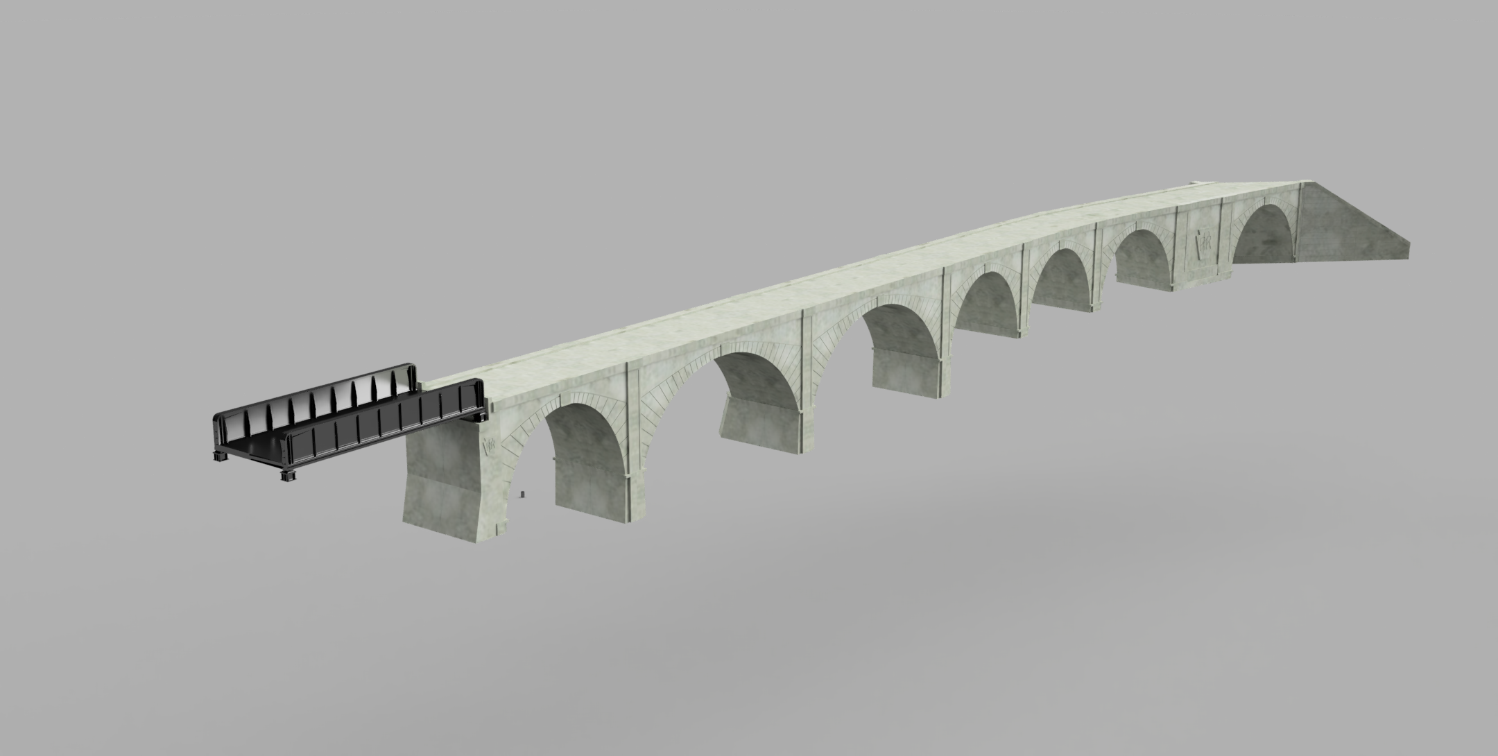
<p>This is an HO scale model of the Pennsylvania Railroad viaduct over the Schuylkill River in Phoenixville, Pennsylvania. The model was developed using information from HistoricBridges.org and Google Maps in Fusion 360.<br><br>For more information and photos of the bridge, follow this link:<br><br>https://historicbridges.org/bridges/browser/?bridgebrowser=pennsylvania/phoenixvilleviaductprroverschuylkill/#photosvideos<br><br>This is the third model in this series, and is quite large and complicated. When I saw this bridge in Google Earth it looked like a scene from a model railroad layout, and the prominent logos should be heart warming to any PRR railfan. If the original bridge was completely modeled it would be over 12 feet long. The model shown is condensed into the minimum required to show all the components, and is almost 6' long in HO scale. The trackbed height with the tall piers is 7" (180 mm), the short piers is 5 7/16" (138 mm), and the default, prototypical width is 4" (104 mm, updated August 16, 2022). Using PrusaSlicer I estimated about 6 kg of filament to print this condensed version of the bridge in HO scale, so you should check everything carefully in both the 3d model and your printer before proceeding on such a monumental project. This is a project that I did to learn Fusion 360 and this model was a big challenge for me. I have shared the model file, but I know there are some embarrassing things in there. After a lot of work, it does what is needed. For other information such as background and print settings, see my Ottawa River Bridge, and for information on Fusion 360 and how to change parameter settings see my Beaver Railroad Overpass.<br><br>The design of this model is intended to allow mixing and matching of components so that it can be fit into varying layouts. Two parameters can be changed: BridgeWidth and SpanAngle. BridgeWidth is the width of the bridge. The SpanAngle parameter is the angle of each side of one half arch (30' long, total of two components) of the 60' span curved section. The default is 2.687 degrees, which should match a 44 inch radius curve at the inside face of the bridge. <br><br>The following is a description of the parts in the order of the prototype, refer to the photo with the key plan of the condensed version of the prototype bridge:<br><br>60 Span RR Rt/Lft - this is the westernmost end of the concrete arch bridge, where a through plate girder bridge connects to cross the old Reading Railroad. Update August 16, 2022 - when I modeled the girder bridge I realized I had not modeled this correctly. I have corrected most of the errors so that the girder bridge will work, although some of the dimensions and the height of the PRR logo are still a little off. Note that this has the shorter pier.<br><br>60 Span Tall Rt/Lft - these are the shorter 60 foot spans on each side of the river that are on the taller piers to match the 90 Spans.<br><br>90 Span Rt/Lft - these are the main 90 foot spans with standard piers for either side of the river.<br><br>90 Span River Rt/Lft - these are the main 90 foot spans with armoring in front of the piers to be used on the upstream side of the bridge in the river. Use the 90 Span Rt/Lft for the downstream side of the bridge.<br><br>60 Span Rt/Lft - These are for the 60 foot spans across the town streets, with the shorter pier.<br><br>60 Span Angle Inside/Outside Rt/Lft - this is a matched set of four pieces that combine to make 60 feet of bridge that is curved to a 44 inch radius in HO scale. Since it is a double track bridge the actual radius of the inside and outside tracks is different. I computed 2.687 degrees to get a 44 inch inside bridge face radius, the angle is the direction change for each half section using the equation atan(length/radius). As explained in the Ottawa Bridge description, the modeling was done so that the sides of the bridge are printed as the top on the 3d printer to get high quality finish. To allow for curves, which seems likely to be wanted for such a long bridge, and avoid side walls that are not horizontal on the print bed, the outside ends of this span are mitered.<br><br>Remaining models - I think this is the most interesting part of the bridge, and was the most difficult to model. See the key plan for all the pieces, there is no point in listing them all here. This is the east end of the bridge and the track to the south east continues on grade. The bridge over Amelia St is at about a 45 degree angle to the tracks, necessitating the double pillar wall decorated with the PRR logo on the south side. Since the sides of the arches are fixed, changes to the width of the bridge will change the angle of this underpass somewhat. There are two retaining walls on the far east side which have some nice reliefs. </p><p>I printed one arch in N scale, and lightly spray painted it with white paint to see how it would look and photograph it. I increased the incise on the PRR logo after this print so that it would look better at N scale. </p><p>Hopefully someone will at least get some inspiration from these models, although it would be great to see them actually used in a layout.</p><p>Update August 16, 2022 - as mentioned above when I modeled the through girder bridge on the west end I realized that the pillar was not correct in several dimensions. I also saw that the bridge I first posted was too wide. Using Google Earth to look at the top of the bridge I saw that the side walls are actually a little higher than the fill of the bridge deck. I think this actually makes the bridge more attractive and included that change in this version. A proper model should also include the handrail. I included the stl of the girder bridge for reference but the openSCAD file will be included with the other openSCAD models since that is where it was developed. Note - I saw that the PRR emblem on the girder bridge side was a little low, so I corrected it.</p><p>Updated August 19, 2022 - updated and fixed some of the stray objects in the girder bridge. This bridge is a composite steel and concrete type, which is not commercially available, so I included a 3mf if someone wanted to print it. I changed the cover photo to show the current appearance. Did not change the .3mf file of the main bridge since only the .f3d file changed.</p>
With this file you will be able to print Phoenixville Viaduct Model Railroad Bridge with your 3D printer. Click on the button and save the file on your computer to work, edit or customize your design. You can also find more 3D designs for printers on Phoenixville Viaduct Model Railroad Bridge.