Physics Gyroscope
thingiverse
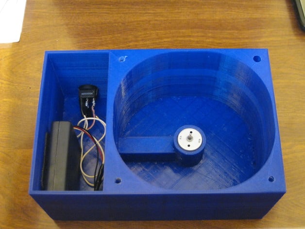
I was tasked with designing and 3D printing a project that would help kids learn in a classroom setting, so I designed a gyroscope. A gyroscope is a device consisting of a wheel or disk mounted to spin rapidly about an axis that can alter direction freely. Gyroscopes are commonly used for navigation systems, auto-pilot in planes, and stabilizers. In this project, a 3D printed wheel with a five-inch diameter and three-quarter inch thickness was created, along with an axle inserted into the center of the wheel and glued to it. The motor, located directly under the wheel, was pressed into the hole on the axle, secured in place by an extrusion. The motor fit snugly so it wouldn't shift or move. In the inner battery compartment, the battery box was stored (I used sticky Velcro to fasten the battery box to the side to prevent movement). On the side of the box, the on/off switch was snapped into its hole. Wires from the battery box and motor were soldered to the on/off switch, completing the circuit. When turned on, the LED light on the switch lit up, and the wheel began spinning at approximately 5000 RPM. After everything was hooked up, the lid could be bolted onto the case. When the wheel reached maximum speed, holding the box with the on/off switch facing upwards and turning it clockwise or counterclockwise caused the wheel to level out. Remember that most parts are plastic and can break easily, so use caution when bolting parts together and handling the project. Print Settings: Printer Brand: Ultimaker Printer: Ultimaker 2 Rafts: No Supports: Doesn't Matter Infill: See misc. notes Notes: Each part's infill is listed here: Axle- 50% infill. Wheel- 40% infill. Box- 10% infill. Lid- 10% infill. How I Designed This: I used Autodesk Inventor 2016 student version for this project. It's a great CAD software, and I highly recommend it. With Inventor, you can design virtually anything. After designing each part, I exported them as a .stl file and opened them in Cura, Ultimaker's 3D printing software. Parts List: Motor: 5000 RPM 6V High Torque Cylinder Magnetic Electric Mini DC Motor http://www.amazon.com/gp/product/B00AUCGG6U?refRID=D9K31CTFQTPS9DACS15S&ref_=pd_ybh_a_23 On/off switch: HOTSYSTEM 10A SPST Automotive Relay Switch http://www.amazon.com/HOTSYSTEM-10A-Automotive-Switch-Single-Pole/dp/B004L3M5OA/ref=sr_1_2?ie=UTF8&qid=1434441110&sr=8-2&keywords=automotive+relay+switch Project: Physics Gyroscope Objectives: By participating in the Physics Gyroscope project, students will learn how a gyroscope works, what type of force it uses, and why it resists movement. Audiences: High school students and college students are targeted for this project because they can understand its actions. Preparation: Before starting, students need batteries, a 5/38 hex screwdriver, and a creative mind. Steps: First, download the attached files and print out the parts. Order recommended parts that cannot be printed. Once you have all essential parts, solder one wire to each pole of the motor. Feed wires through the tunnel from the motor end so they come out the other side. Push the motor down into the extrusion. Feed those same two wires through the hole for the switch and solder them to the outer prongs on the switch. Feed wires from the battery box through the hole for the switch. Solder the positive wire from the battery box to the middle prong of the switch. The other wire (negative) gets soldered to the gold prong on the switch. There should be one wire on the outer, silver prong, one wire on the silver, middle prong, and two wires on the outer, golden prong. Snap the switch into its hole. Put the lid on, but before you do that, make sure the switch on the battery box is on. Set the lid on top and bolt it on. Results: At the end of this project, students will have made a working gyroscope. They will be able to feel the force acting upon it, and they will have learned why that force is there. In order to get a grade, the student will fill in a paper describing how it works, how well it works, and how long it took them to make it. The paper should be like a science lab report over the gyroscope.
With this file you will be able to print Physics Gyroscope with your 3D printer. Click on the button and save the file on your computer to work, edit or customize your design. You can also find more 3D designs for printers on Physics Gyroscope.