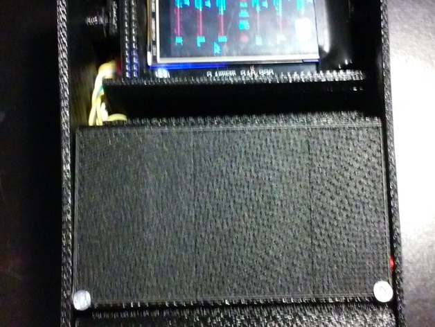
Pi-Corder Case

Pi-Corder Case

thingiverse

This project provides a portable case for Raspberry Pi 2 or B+ in the form similar to a Star Trek TOS "Tricorder". The inspiration was from: A need for a solid and durable form factor for a portable RPi case with display. Several very good Star Trek NexGen tricolor case projects here on Thingiverse. Hackaday.io project by Rob Vincent that uses a toy case. This design has a swivel top for a Swainsmart 2.4" TFT 240x320 display. It has plenty of room for an internal battery, speaker, and a spot for small sensors/GPIO projects (my pictures include a GPS). To Do: The swivel assembly needs work, it is difficult to assemble and potentially fragile. Perhaps pins added from the outside in, instead of the inside out. (Tried - was worse than wood/metal pins, so widened swivel holes to .14 radius). (Done) Change from glue only assembly to a less permanent screw together design. I've marked it complete, but I still might tinker with it. Print Settings Rafts: Yes Supports: No Notes: Print the right wall with Y-axis rotated 90 degrees. Print the cover with the X-axis rotated 90 degrees. Print the left wall with the Y-axis rotated 270 degrees. Print the top with the X-axis rotated 180 degrees. Detailed directions attached. Build Instructions Materials Note: Raspberry Pi 2 Sainsmart 2.4TFT 240x320 Display -Note: Perhaps mods for Adafruit PiTFT 2.4” HAT Mini Kit (4) 1/2” Standoffs and mounting hardware SPST Switch USB to Mini-USB Cable USB Universal Power Battery Pack (Optional: Parallax PMB-648 SiRF Module) (Optional: USB 802.1 Wireless Network adapter) 16G SMC Memory Card Stereo Headphones or small speaker with headphone jack. Number 4 x 1/2 Wood Screws 1/4" Wood Dowel or Metal Rod (preferred) Construction Notes: Print the base (make sure the sides are flat), mount the standoffs and then mount the board. Connect the display cabling shown below: Connections for SainSmart 2.4” TFT Display to RPi B (40-pin): LCD Name Driver Name RPi Name RPi Pin Vcc \ \ 2 (Vcc Bus) Gnd \ Gnd 6 RS dc GPIO3 5 WR wr GPIO2 3 RD \ 3.3V 1 DB8 db00 GPIO5 29 DB9 db01 GPIO6 31 DB10 db02 GPIO18 12 DB11 db03 GPIO23 16 DB12 db04 GPIO24 18 DB13 db05 GPIO25 22 DB14 db06 GPIO8 24 DB15 db07 GPIO12 32 CS cs GPIO27 13 REST reset GPIO17 11 LED led GPIO4 (or Vcc Bus) 7 via transistor to Vcc ——————————————————————— Touch Screen Inputs T_CLK SCLK 23 T_DIN MOSI 19 T_DOUT MISO 21 T_CS CEI 26 T_IRQ GPIO16 36 ——————Removed as it requires too much current ———————————————— Parallax PMB-648 SiRF (GPS) Module Pin 1 on GPS (Yellow/TTL TX) to Pin 10 on P1 connector of Rip Pin 2 on GPS (Blue/TTL RX) to Pin 8 on P1 connector of RPi Pin 3 on GPS (Red/Vcc) to Pin 2 or Pin 4 on P1 connector of RPi Pin 4 on GPS (Black/Gnd) to Pin 6 or Pin 9 on P1 connector of RPi —————————————————————------------------------------ Recommend that the following connections be extended to the module bay (and marked): Pin 8: RX (for GPS or serial) Pin 10: TX (for GPS or serial) Pin 3: +5Vcc Pin 38: GPIO 20 (for other projects) Pin 39: Gnd Pin 40: GPIO 21 (for other projects) It is strongly recommended to verify all hardware at this time: Charge up the battery pack several times. Verify the power switch functions correctly. Perform the initial install/uipdate of OS and Display. Print the right wall with Y-axis rotated 90 degrees. The power switch can be mounted to the inside of the “Module Bay”. Print the cover with the X-axis rotated 90 degrees. Drill out the mounting holes for the cover in the right wall. Plug in the USB Power Cord and Headphone jack, then screw the right wall to the base. Insert the USB Battery Pack in the Battery Bay and use clay or putty to affix the pack in the bay so that the power connection can match up on the port on the left side. Print the left wall with the Y-axis rotated 270 degrees. Glue the left wall to the case. Print the top with the X-axis rotated 180 degrees. Sometimes the hole for the pivot pin will need to be cleaned out. While the design is a.25” diameter hole, practice showed it was about .2”. I used a sanded 1/4” dowel. Slide the top into place and add the pins. Screw in the display. OS Install Notes: Do you updates: sudo apt-get update sudo apt-get upgrade ---------Add to /etc/modules-load.d/fbtft.conf (may need to create this file)------ spi-bcm2835 fbtft_device ads7846 -------Add to /etc/modprobe.d/fbtft.conf (may need to create this file)------- options fbtft_device name=itdb28 gpios=reset:17,dc:3,wr:2,cs:27,db00:5,db01:6,db02:18,db03:23,db04:24,db05:25,db06:8,db07:12,led:4 rotate=90 options ads7846_device swap_xy=1 cs=1 speed=1000000 model=7846 x_min=300 x_max=2400 y_min=700 y_max=3200 x_plate_ohms=60 pressure_max=255 gpio_pendown=16 keep_vref_on=1 ------Add to /boot/config.txt---for touch screen input------- dtparam=spi=on dtoverlay=ads7846,speed=1000000,penirq=16,penirq_pull=2,xohms=150,swapxy=1 ============================== Pre-Jessie: add display to /etc/modules: ———— modprobe fbtft_device name=itdb28 gpios=reset:17,dc:3,wr:2,cs:27,db00:5,db01:6,db02:18,db03:23,db04:24,db05:25,db06:8,db07:12,led:4 ——— add tft to /boot/config.txt: dtoverlay=ads7846,speed=1000000,penirq=16,swapxy=1 —— For GPS: If GPS, disable serial port from raspiconfig. sudo apt-get install gpsd sudo apt-get install gpsd-clients Add to /etc/rc.local with: “gpsd /dev/ttyAMA0 -F /var/run/gpsd.sock" Change to Headset jack: sudo amixer cset numid=3 1 Highest volume: amixer cset numid=1 -- 400 Playing a video loop to spoof a TOS Scanner: Jessie: sudo SDL_VIDEODRIVER=fbcon SDL_FBDEV=/dev/fb1 mplayer -vo sdl -framedrop scan.mp4 PreJessie: mplayer -vo fbdev2:/dev/fb1 -x 320 -y 240 -loop 20 -framedrop -zoom scan.mp4

Download Model from thingiverse

With this file you will be able to print Pi-Corder Case with your 3D printer. Click on the button and save the file on your computer to work, edit or customize your design. You can also find more 3D designs for printers on Pi-Corder Case.