Pico Development Board
prusaprinters
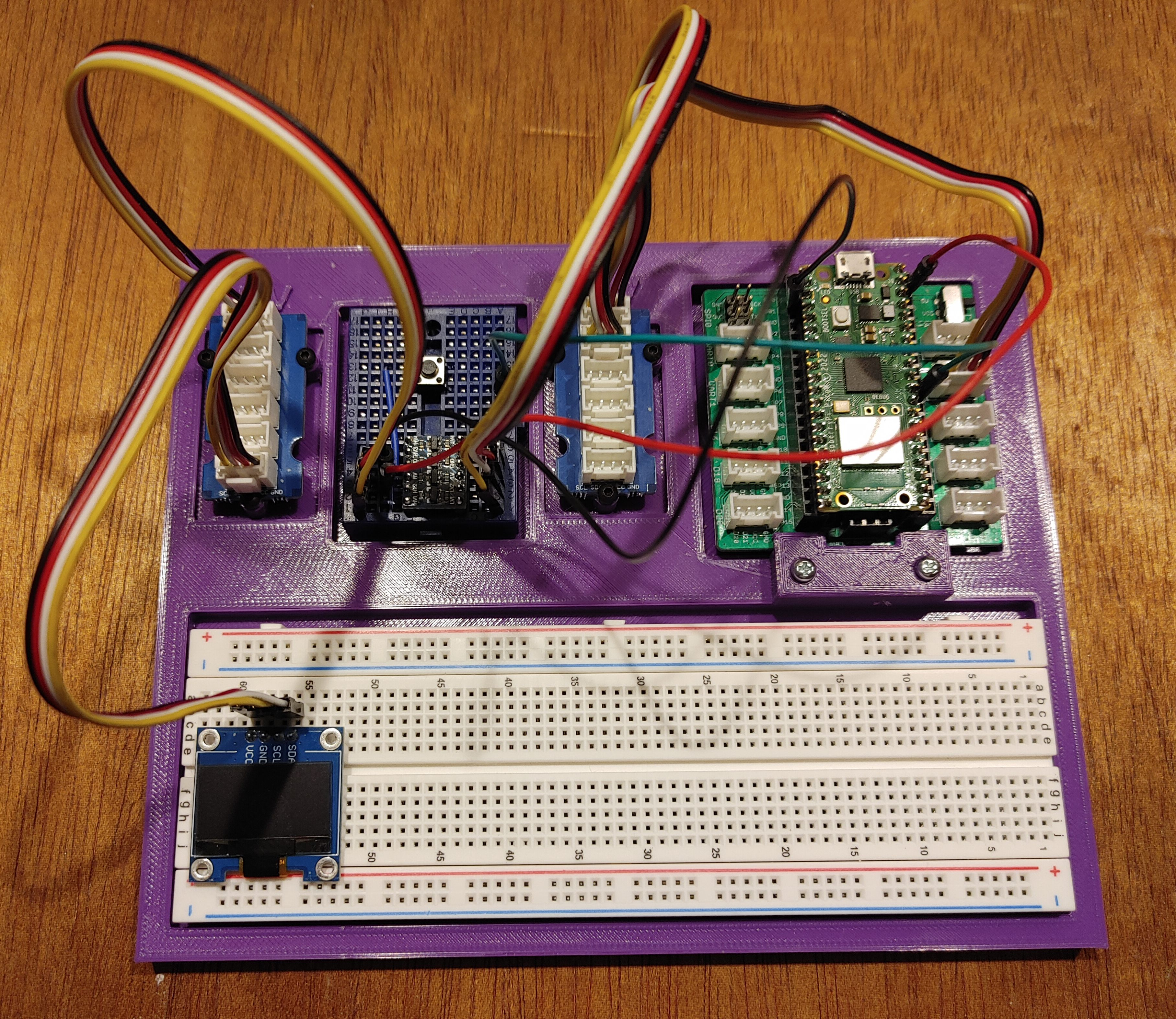
<p>The Pico Development Board is used to bring all the components in your Pico/Circuit development into one place. This makes it easy to move you setup and not worry about all the individual components that are held together by just jumper wires.</p><p>The development board has room for a full size breadboard (830 Point Solderless Prototype PCB Board), a min breadboard (with no power/ground buses), two Grove I2C Hubs, a Grove Shield for Raspberry Pi Pico, a logic level shifter, and a run push button switch.</p><p>There are two Grove I2C Hubs in order to dedicate one hub to 5V I2C devices and the other to 3.3V I2C devices. The Pico/Pico W can communicate with both hubs, directly with the 3.3V hub and through the logic level shifter to the 5V hub.</p><h3>Assembly</h3><ol><li>Print the Pico Development Board</li><li>Print the Pico Mount Lock</li><li>Remove the paper on the bottom of each breadboard, exposing the sticky surface, and place the breadboards in their appropriate indentations on the development board.<ol><li>My preference is to have the tabs on the sides and ends of the breadboard face the center of the development board. This places row 1 of the full size breadboard at the end with the Pico.</li></ol></li><li>Mount the two Grove Hubs on either side of the mini breadboard. Each hub uses three of the M2x6 screws.</li><li>Place the Grove Shield for Raspberry Pi Pico on top of the posts in its indentation so that the USB end of the Pico is facing the outside of the development board.</li><li>Mount the Grove Shield with two M2x6 screws using the screw holes at the USB end of the shield.<ol><li>Note, the M2x6 screws will not fit in the other two screw holes because the headers on the shield get in the way of the screw heads.</li></ol></li><li>Insert the Pico Mount Lock into the two larger holes in the center side of the shield so that the two tabs are over the shield.</li><li>Mount the Pico Mount Lock with two M2.5x12 screws.<ol><li>The Mount Lock is used to do the job of the two screw holes are are unusable.</li></ol></li><li>Insert a Raspberry Pi Pico or Raspberry Pi Pico W into the Grove Shield.</li><li>Use the 4 pin Grove Cable with Grove Connectors on both ends into either the I2C0 or the I2C1 Grove socket on the shield.<ol><li>A Grove to Grove cable comes with the Grove I2C Hub</li></ol></li><li>Plug the other end of the Grove Connector Cable into one of the sockets on the 3.3V hub.<ol><li>Note. The development board labels each hub as either 3.3V or 5V.</li></ol></li><li>Plug a Grove to 4 Pin Male connector into the 3.3V hub.</li><li>Plug the four pins of that cable into the low voltage side of the logic level shifter.<ol><li>Make sure to plug the cable pins into the appropriate pins of the logic level shifter so that the shifter pins [GND, LV (lower voltage), LV2, LV1] are connected to the Hub cables [Gnd, Vcc, SDA, SCL]</li></ol></li><li>Plug a Grove to 4 Pin Male Connector into a socket of the 5V hub.<ol><li>Make sure to plug the cable pins into the appropriate pins of the logic level shifter so that the shifter pins [GND, HV (higher voltage), HV2, HV1] are connected to the Hub cables [Gnd, Vcc, SDA, SCL]</li></ol></li><li>Connect the Vsys pin (physical pin 39) on the Pico to the HV pin of the logical level shifter with a dupont jumper cable.</li><li>Connect any GND pin (physical pins 3, 8, 13, 18, 23, 28, or 38) on the Pico to the GND pin on the HV side of the logic level shifter with a dupont jumper cable.</li><li>Connect one of the GND pins on the logic level shifter to one side of the push button switch.<ol><li>It does not matter which ground pin from the logic level shifter since they are both grounded to the Pico.</li><li>Instead of connecting the push button switch to the logic level shifter ground, the button can be connected to one of the ground pins on the Pico though this uses up one of the available grounds on the Pico.</li></ol></li><li>Connect the other side of the push button switch to the Pico Run Pin (physical pin 30)</li></ol><p> </p><h3>Parts List</h3><ul><li>Pico Development Board – printed</li><li>Pico Mount Lock – printed</li><li>1 -<a href="https://smile.amazon.com/gp/product/B08DFWQBMB/ref=ppx_yo_dt_b_search_asin_title?ie=UTF8&psc=1"> Full Size Breadboard – 830 Point Solderless Prototype PCB Board</a><ul><li>The place to develop your circuits.</li></ul></li><li>1 - <a href="https://smile.amazon.com/gp/product/B07LF71ZTS/ref=ppx_yo_dt_b_search_asin_title?ie=UTF8&psc=1">Mini Breadboard – 170 Point Solderless Prototype PCB Board</a><ul><li>This small breadboard is used for the permanent placement of the logic level shifter and the run button.</li></ul></li><li>1 - <a href="https://smile.amazon.com/gp/product/B07YZTW2SM/ref=ppx_yo_dt_b_search_asin_title?ie=UTF8&psc=1">4 Channel I2C Logic Level Shifter</a><ul><li>The Logic Level Shifter allows the Pico to control I2C devices that require 5V to operate by shifting or converting the Pico 3.3V signals to 5V. The logic level shifter is bi-directional.</li></ul></li><li>1 - <a href="https://smile.amazon.com/gp/product/B07YZTW2SM/ref=ppx_yo_dt_b_search_asin_title?ie=UTF8&psc=1">1 Momentary Tactile Push Button Switch</a><ul><li>Operates the Run Pin on the Pico.</li><li>Pushing the Run button and the BootSel button down together, releasing the Run button first, works the same as holding the BootSel button down while connecting the USB cable. The Run button is less wear and tear on the USB socket.</li><li>Any momentary push button switch that can be mounted on a breadboard will do. There are larger push buttons switches available that can be easier to push.</li></ul></li><li>2 - <a href="https://www.robotshop.com/en/grove-i2c-hub-6-port.html">6 Port Grove I2C Hub</a><ul><li>Two hubs are used to accommodate I2C devices that require 5V to operate and I2C devices that require 3.3V to operate.</li><li>The Logic Level Shifter allows 5V I2C signals to be converted to 3.3V signals, allowing the Pico to control both set of I2C devices.</li></ul></li><li>1 - <a href="https://thepihut.com/products/grove-shield-for-raspberry-pi-pico-v1-0?variant=41952985448643">Grove Shield for Raspberry Pi Pico v1.0</a><ul><li>The Grove Shield is a breakout board for the Pico/Pico W with 10 Grove sockets that connect to various GPIO pins.</li><li>The headers that hold the Pico onto the shield are 2x20 so that there is place for a jumper wire to connect to each pin on the Pico.</li><li>There are four screw holes in the shield that line up with the screw holes in the Pico. Unfortunately, the headers on the board do not leave enough space for the head of the screws, hence the need for the Pico Mount Lock.</li></ul></li><li>8 - <a href="https://smile.amazon.com/gp/product/B01B1OD9UQ/ref=ppx_yo_dt_b_search_asin_title?ie=UTF8&psc=1">M2x6 Screws</a><ul><li>Holds each of the Grove Hubs (3 screws each) and the Grove Shield (2 screws)</li></ul></li><li>2 - <a href="https://smile.amazon.com/gp/product/B000NHXNWW/ref=ppx_yo_dt_b_search_asin_title?ie=UTF8&psc=1">M2.5x12 Screws</a><ul><li>Holds the Pico Mount Lock in place.</li></ul></li><li>4 - <a href="https://smile.amazon.com/gp/product/B07GD431C1/ref=ppx_yo_dt_b_search_asin_title?ie=UTF8&th=1">Dupont Jumper Cables – Male to Male</a><ul><li>The 15 cm length jumpers should work in this case. The 10 cm length jumpers may work but will be a bit tight.</li></ul></li><li>2 - <a href="https://www.bananarobotics.com/shop/Grove-4-Pin-Connector-to-Male-Jumper-Wire-Cable-5-pack?search=grove">Grove to 4 Pin Male Connectors</a><ul><li>These connectors are used to connect the Grove Hubs to the mini breadboard and the logic level shifter.</li><li>There are at least two types of Grove connectors. The difference between them is some have clips to hold the connector in the socket and the others do not. The 6 port Grove Hubs are placed close together. Both types of connectors work with the hubs while the clipless ones are easier to remove.</li><li>Grove to 4 Pin Female Connectors will connect directly to I2C devices that you do not want to mount on the full breadboard.</li></ul></li><li>1 - <a href="https://www.newark.com/raspberry-pi/raspberry-pi-pico/raspberry-pi-board-arm-cortex/dp/22AJ1097?st=raspberry%20pi">Raspberry Pi Pico</a> or <a href="https://thepihut.com/products/grove-shield-for-raspberry-pi-pico-v1-0?variant=41952985448643">Raspberry Pi Pico W</a><ul><li>Both the Pico and the Pico W fits in the socket of the Grove Shield.</li></ul></li></ul><h3> </h3><h3><strong>Print Settings</strong></h3><h4><strong>Printer:</strong></h4><p>Creality Ender 3 Pro</p><h4><strong>Supports:</strong></h4><p>No</p><h4><strong>Resolution:</strong></h4><p>0.2 mm</p><h4><strong>Infill:</strong></h4><p>20%</p><h4><strong>Filament:</strong></h4><p>PLA or PLA+</p>
With this file you will be able to print Pico Development Board with your 3D printer. Click on the button and save the file on your computer to work, edit or customize your design. You can also find more 3D designs for printers on Pico Development Board.