Picoscope- DIY SmartPhone Oscilloscope using Raspberry Pi Pico
thingiverse
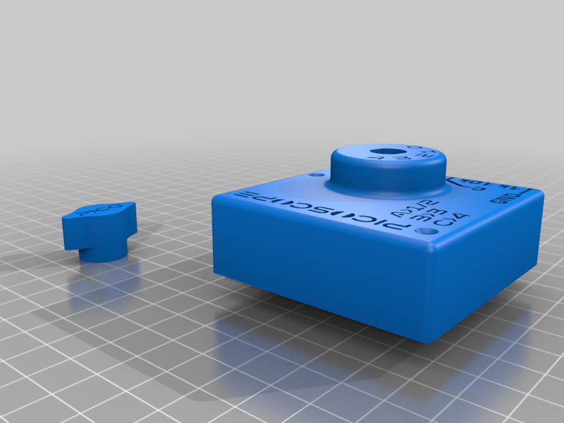
Sometimes when you repair some electronics hardware and do some Research and Development work, you need an Oscilloscope. You can use multimeters as well, but the problem with multimeters is that they aren’t fast enough to detect the signals. There is a standard oscilloscope for lab and industrial applications. When you go through the pricing of a commercial oscilloscope, you will realize it is not affordable for beginners. If you are an electronics hobbyist or some technician and if you are unable to buy these, then here is a solution for you. We can design a simple DIY SmartPhone Oscilloscope using a microcontroller at a very low price probably at 5$ only. Read further from https://how2electronics.com/diy-smartphone-oscilloscope-using-raspberry-pi-pico/ This model uses the rotary switch circuit to shift between voltage dividers to make it feasible for the pico to measure safely. Circuit diagram- https://how2electronics.com/wp-content/uploads/2022/02/DIY-SmartPhone-Oscilloscope-1-580x439.jpg The rotary switch is taken from an old ceiling fan speed regulator. This has 5 steps. The resistors i have used in series are 100k,100k,10k,1k. You may need to give support for printing the top cover. Please use aligator clips to connect the testing device.
With this file you will be able to print Picoscope- DIY SmartPhone Oscilloscope using Raspberry Pi Pico with your 3D printer. Click on the button and save the file on your computer to work, edit or customize your design. You can also find more 3D designs for printers on Picoscope- DIY SmartPhone Oscilloscope using Raspberry Pi Pico.