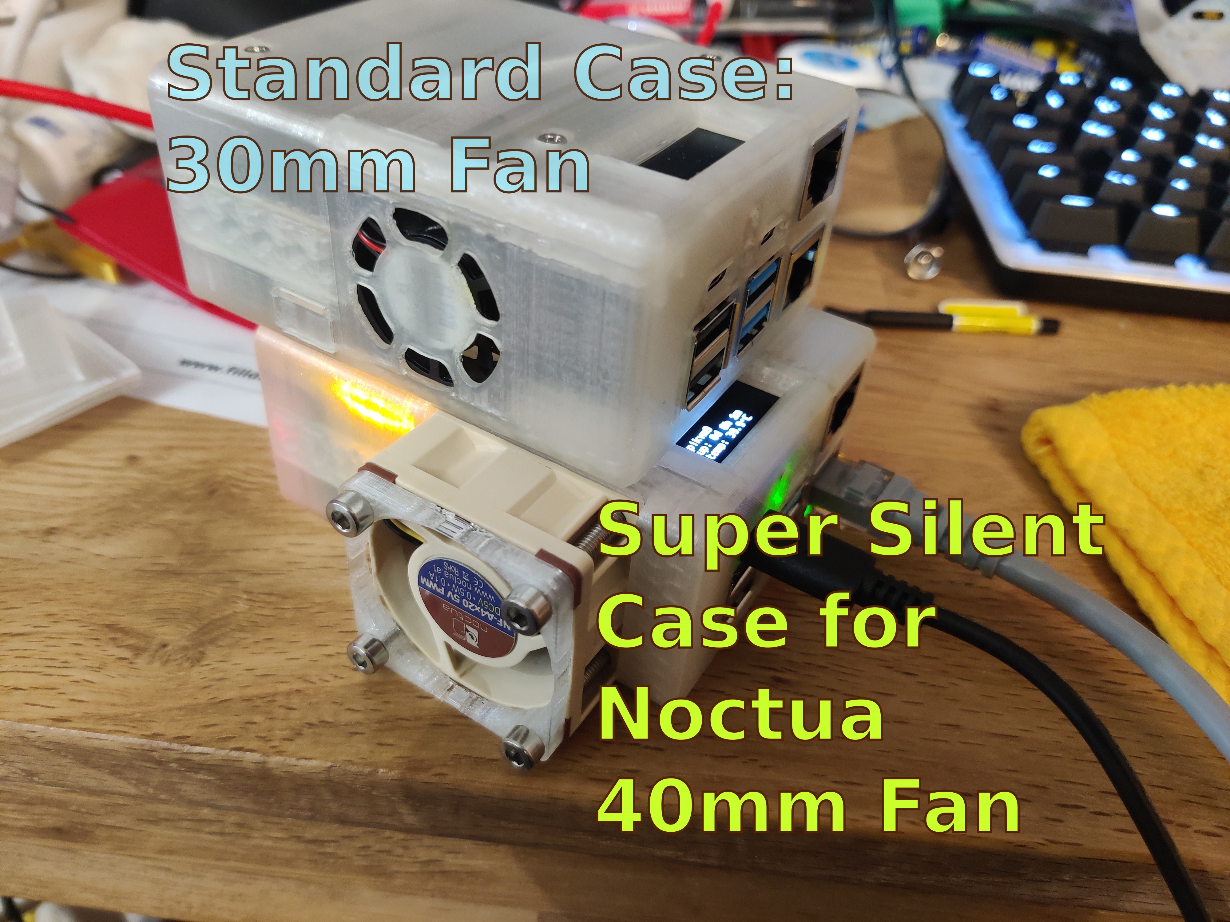
PiKVM Case Mod for silent Noctua 40mm Fan
prusaprinters
<p>This is a remix of the original Case published here: <a href="https://docs.pikvm.org/stl/v3.3/">https://docs.pikvm.org/stl/v3.3/</a></p><p>The original case is just fine when placed into one of those dedicated server rooms which tend to be extremely loud with hundreds of fans of all sizes screaming at you with insane RPMs.</p><h3>Motivation</h3><p>The PiKVM is a great device, there is no doubt about that. I use one in my lab which is in general completely silent. The original 3D printed case allows room for a 30mm fan which is powerful enough to keep even the Pi4 cool. However, I could not find any high quality fan of this size. Manufacturers known to make perfect fans do not have a 30mm model, they start at 40mm.</p><p>The 30mm one I got off of Amazon is crap and I had no idea which ones are good since they are all made by unknown brands.</p><p>So I decided that I wanted to use a 40mm fan to keep the PiKVM unit cool. This required some modifications to the "A" part of the 3D printed case.</p><h3>Changes</h3><p>This is a description of all the changes I made.</p><h4>The case</h4><p>I loaded the publicly available STL file into Onshape because Debian decided to remove FreeCAD completely from Debian Testing, which happens to be my main OS. I wanted to try Onshape for a while now and FreeCAD drives me insane anyway.</p><p>I just cut out a 41mm squared block and made sure that there are means to bolt the fan onto the case. It sticks out a little bit but the case is still able to sit flat on the table. The fan is placed so that it evacuates the case just like in the original design.</p><p>There is also a small spacer for the fan because I only had M4x30 screws and they were about 5mm too long and were going to hit the mainboard. If there are M4x25mm screws available the spacer can and must be removed.</p><h4>Electronics</h4><p>First I tried the on board fan header. It worked but in the area of about 25% to 33% the RPMs of the fan kept oscillating and this was audible. Above and below it was fine but all in all not perfect.</p><p>I tried hooking up the fan to 5V and connecting its PWM line to the fan header. This did not yield the desired results. Time for some thinking, reading and additional hardware.</p><p>I got myself my first oscilloscope, read everything I could find on the design of the PiKVM's fan header and put the conclusions together.</p><p>I tried connecting the PWM line to GPIO pin 12 which is used in PWM mode to drive the fan header anyway and it worked out of the box. Using the built in fan controller I could control the fan from 5% (yes, five, not fifty and it ran smoothly) all the way up to 100% without any issues whatsoever. Note: per default the pin ist set to a so called “PWM Balanced” mode. This mode violates the specification of how the PWM pin of a fan is to be used. However.. the Noctua fan didn't care and performed its task perfectly. Noctua fans are awesome. You may think that I could call it a day but no, there is more.</p><p>There was a tacho line dangling unused at the fan and the fan controller has an option to specify an RPM pin to watch over the fan. So I picked a free GPIO pin (I chose 25) and connected the tacho line to it. It did not work. The oscilloscope showed that the signal on that line was garbage. With my limited background in electrical engineering I tried a 1k pull up resistor and behold, it worked! Further reading about pull up resistors revealed that they are usually between 10k and 100k. So my 1k was not perfect and I switched it for a 47k resistor. It did work but the signal was strangely deformed like there was a voltage divider at play here. I read some more about internal pull up resistors of the Pi4 and realized that the pin was set to utilize a 50k pull down resistor. The 1k I tried at first overruled it completely but the 47k one compared with the 50k internal one indeed acted as a voltage divider. So I changed the config to pull up, removed the 47k external pull up and the signal was as clear as can be. No need for an additional part. The fan controller worked perfectly with the modifications.</p><h5>Wiring Diagram</h5><p>Noctua fans have a standardized wire color scheme.</p><figure class="image"><img src="https://media.printables.com/media/prints/218724/rich_content/dd35a733-3727-4b13-9950-31bad6bb1ab3/pwm_fan_wiring.png#%7B%22uuid%22%3A%22718074c4-6749-40ba-a7bc-dc1ec5a59af7%22%2C%22w%22%3A1339%2C%22h%22%3A1000%7D"></figure><h3>Configuration</h3><p>There is only one place where the default configuration needs to be adapted to work perfectly. </p><p>The configuration for the fan controller:</p><pre><code class="language-plaintext">[root@pikvm ~]# cat /etc/conf.d/kvmd-fan KVMD_FAN_ARGS="--verbose --speed-idle 5 --speed-low 5 --temp-low 30 --speed-high 50 --temp-high 55 --temp-hyst 3 --hall-pin 25 --hall-bias 2"</code></pre><p>All in one line. The big fan is much more powerful than any 30mm variant so the speeds as well as the temperatures are lower.</p><h3>Required Hardware</h3><p>This is a complete list of all the additional parts I used</p><ul><li>Noctua NF-A4x20 5V PWM (but any 40mm fan will do with varying quality)</li><li>4x M4x25 or M4x30 (use spacer) button head screws. Use shorter screws if your fan is not 20mm high</li><li>Sockets to solder on individual wires</li><li>Colorful heat shrink tubing</li></ul><h3>Assembly</h3><p>Follow these easy steps to put it all together.</p><ol><li>Print all the parts. Instead of the original case_a.stl print the modified one, print the spacer if needed.</li><li>Cut off the original fan connector, leaving enough wire length</li><li>Route the fan wires so that they come out at the front (intake) side of the fan</li><li>Solder connectors/sockets onto the fan's wires</li><li>Put the fan with its intake side towards the inside of the case in its cut out space</li><li>Ensure that the wires go through the small opening in the case and do not block the airflow</li><li>Secure the fan with 4x M4 screws</li><li>Connect the fan to the board</li><li>The black (-) and the yellow (+) wires go on the 5V header next to the built in fan header</li><li>The green (RPM/tacho) wire goes to GPIO-25</li><li>The blue (PWM) wire goes to GPIO-12</li><li>Insert the board into the printed case_a part ensuring that the wires are routed neatly</li><li>Continue assembly with the original design</li><li>Apply the config changes</li><li>Ensure everything is good, fine tune config if needed.</li></ol><h3>Final words</h3><p>Now my lab will be silent again. At ~24% power the temperature settles at ~40°C. I have to put the modified PiKVM as close as 20mm to my ear in order to hear it as loud as the unmodified one that resides in a closed rack that is placed around the corner and needs 50% power to hold the same temperature. It is actually louder with lower power settings because the higher magnetic force keeps it from rubbing on its own frame.</p>
With this file you will be able to print PiKVM Case Mod for silent Noctua 40mm Fan with your 3D printer. Click on the button and save the file on your computer to work, edit or customize your design. You can also find more 3D designs for printers on PiKVM Case Mod for silent Noctua 40mm Fan.