Platform Collision Saver and E-STOP
thingiverse
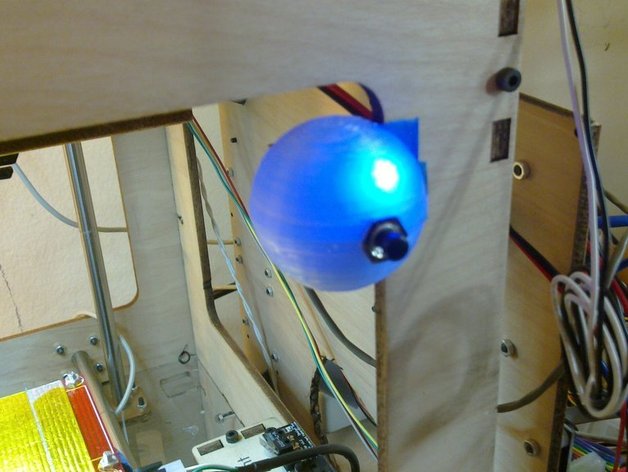
This thing is meant to protect you from the agony of destroying your Thing O Matic or Cupcake heated build platform PCB by putting your print head through it. It can happen to the best of us. It is a simple circuit that plugs into the EMERGENCY STOP port on a Thing-O-Matic, although I can easily set it up to work the same way for Cupcake users. Two wires go to your print head and aluminum heat spreader, and detect when they have collided. While I have a youtube video of the trial run and it worked quite well, this is a Work-In-Progress for the following reasons: I don't want to be responsible for the $30 for a new platform if you destroy yours, or the new mobo if this fries it, for that matter. Either know enough to know this works or wait 'till someone who does has a good look at it. Needs me to get up the guts to really test it through kapton. UPDATE: I got the guts - and springs for safety. It will not punch kapton when moving only in Z, but it will when moving in X+Y as well which is common during a print, obviously. Video of punch test fail here (not very interesting): youtube.com/watch?v=7x6tTmTuSH0 Needs someone who actually knows electronics to audit my work. Needs a cupcake version? Needs to be tested during an actual print. Does molten PLA/ABS conduct? I /will/ be addressing all of the above, but if anyone can beat me to them, ... thank you! (Please build your own, do not come to my house to fix things!) Feedback on how things /should/ be handled is welcome in the comments. It really NEEDED a test, so as the inventor, it's only right I be the one with a broken heater board if it doesn't work... WARNING: THE FOLLOWING YOUTUBE VIDEO CONTAINS GRAPHIC FOOTAGE OF WHAT HAPPENS WHEN YOU LET YOUR PRINT HEAD COLLIDE WITH YOUR PLATFORM BY INTENTIONALLY SETTING Z NEGATIVE IN YOUR GCODE. IT IS NOT FOR THE SQUEAMISH, YOUNG, OR PEOPLE WITH HEART CONDITIONS. You have been warned. The gcode that was executed was set to move the head to negative Z, then return to positive 30mm Z. It never completed its voyage. I'll tell you now there was no damage and it all worked fine, but it can still be harrowing to watch. And how do you think I felt doing it! http://www.youtube.com/watch?v=oDzqlONX7w4 UPDATE: (2011-02-27) Designed a case, and added a switch to trigger the emergency stop manually. The photos here don't show the (10k) resistor I should have put on the switch... It's not the end of the world; I'm sure the output of the chip is current-limited, but it's not great. The case design is perfect except I made the dimension of my wood a little too large so it is loose; added some bluetape to make it fit. UPDATE: (2011-03-08) The latest version of my firmware includes fixes to this that make the estop button work anytime, on all axes. You get get it at my github! Instructions SOFTWARE: As it turns out, the emergency stop plug on the Thing O Matic is programmed to do nothing. If I'm lyin', someone correct me, but after thorough investigation of the latest source, I was unable to find anywhere the ESTOP_PIN configuration setting was actually /used/. The attached firmware is the stock Thing O Matic motherboard firmware, except the estop pin has been hardcoded for the purposes of this hack. It is normally set to +5v with an internal pullup resistor. If it is pulled down to GND externally then it: a) Shuts down all steppers UNTIL YOU REBOOT. There's no other way out. b) Changes from an input at +5v to an output at +5v, providing power to the LED in this circuit. IF YOU DO NOT USE THE ATTACHED FIRMWARE, THIS CIRCUIT WILL DO NOTHING! Patch file will be supplied detailing the source code changes shortly. HARDWARE: What you need: 1 10,000ohm resistor. Some bits of wire. To make it cooler, add: 1 100-200ohm (ish) resistor - match the exact value of this with your LED. 1 LED - if you can, take note of it's voltage drop and current, then match the resistor to make it light up on 5v. If you dunno, just use a resistor of 100 or a bit more. To make a clean connection to the mobo: 1 old CD-ROM drive audio cable. Remember those? Fits the emergency stop port perfectly. To make the printable LED case: Use transparent PLA. If you don't have any, you can drill a hole for your LED, or redesign. The switch is a simple momentary contact pushbutton from the bin at Radio Shack. Just follow my AWESOME CRAYOLA CIRCUIT DIAGRAMS, and I'm sure you'll be fine. In the photo of the LED assembly, the end labeled 'estop' is plugged into the estop pin. The other end can be attached to any ground; the middle two pins on the estop port are both ground. In the photo of the resistor, imagine if you cut one of the legs in half, wire one end to the print head, and the other end to the heat spreader. It doesn't particularly matter which is which. Again, the label 'estop' end is plugged into the estop pin. The other labels are 'platform' and 'head' if you can't make it out. More photos and better diagrams to come. You don't have to have springs on your build platform and nozzle like I do BUT I BET IT HELPS. :) Basically attach one end to your hot end by any means you like (put it under a nut?) and attach the other end to your heat spreader by any means you like (put it under some kapton tape?). BEFORE YOU GO: TEST IT. Hook it all up, get a jumper wire, and touch it between your aluminum heat spreader and the nozzle. NOTE (currently) this will only have any effect if one or more steppers are in motion when you do it, making it admittedly tricky.
With this file you will be able to print Platform Collision Saver and E-STOP with your 3D printer. Click on the button and save the file on your computer to work, edit or customize your design. You can also find more 3D designs for printers on Platform Collision Saver and E-STOP.