plot thermometer / clock for 3D printers
thingiverse
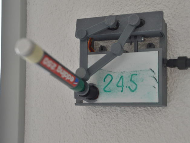
Update #5: Description of the calibration process -> Instructions Update #4: Minor bug fix in the Calibration routine -> v1_1b Update #3: Improved servo arm attachment. See Instructions Update #2: Additional version of the servo arms. See Instructions Update #1: Videos of the plot thermometer/clock: http://youtu.be/0nTKUaYZzgA and http://youtu.be/XSc-_maon80 (please see further update info under instructions) This plot thermometer and plot clock is based on http://www.thingiverse.com/thing:248009 and http://www.thingiverse.com/thing:255608 Initially only with the intention to replace the screws with printed hinges I made several improvements: Hardware: Printed hinges Fully cover of the electronics Covered servos Thermal measurement Integrated switch and power jack Hooks for wall mounting I2C connector for further enhancements like motion sensor etc. mechanical stability FDTI programming port for the arduino Magnetic drawing board holder Software: Inline calibration & setup (use x when connected to a 9600 serial terminal) EEPROM storage of the calibration values temperature measurement capability based on a DS18B20 possibility to choose between time and temperature display Display flip capability (for wall mount) switch for multiple functions (temperature or time / plot on or off) Instructions Update #5 Calibration instructions: Assemble the first part of the servo arms to the servos but don't assemble the second part which holds the pen Attach the arduino (with a FDTI) to a serial terminal program e.g. the one is integrated in the arduino IED ! all Inputs must be finished wit a return! press x (Enter) ! you should see now the calibration menu on the screen. If not it was probably already in the calibration mode. so press x (Enter) again press A (Enter) to recall the default calibration values. press 1 (Enter) the left servo arm should move. With + / - (always followed by Enter) you can bring them in a horizontal position. If you cant reach the horizontal reteach the arm to the servo. press 2 (Enter) do the same for the right arm press 3 the left arm should now stay vertical and the right horizontal. with + / - you can adjust the vertical position press 4 and do the same for the other arm. Toggle between the 3 and 4 position and correct. if the arm which should be horizontal is not in the correct position correct that with 1 or 2. Where the arms are by 1 and two isn't that important the position with 3 & 4 must be precise. press B (Enter) to store the values so far. mount the arms complete and attach a pen. press 9 for a middle position. press 7 to lift the arm maximum press 8 to position the pen over the swee. adjust the arm high with +/- that the pen comes over the top of the swee. press 6 for the height of the pen when it swipe out the ink. adjust with + / - press 7 to lift the pen over the swee press 9 for a middle position press 5 for the pen hight when it should write to the board and adjust with + /- store the values with B now you are done go back to normal operation with x Update #3: A new servo arm (2_3a) to improve the attachment of the servo arms on the servo's. The original servo arm can be glued int them. This provide an optimal fit to the servo. Update #2: Based on a post from #Orictosh stl's from servo_arm_1 and servo_arm_2 turned into the position as they are required to print v2 of servo arms added: The hinge isn't printed any more, they are fixed with a joint (turn it 90 deg. to fix it). For this alternative servo arms you require 1 servo_arm_v2_1, 1_v2_2, 2 _v2_3 and 3 servo_arm_joint Update #1: The hight_servo_arm might touch the board therefore an improved _2 version uploaded The wiring diagram uploaded The program version 1_1 uploaded with this updated software a PIR or a tactile switch enhancement as described in http://www.thingiverse.com/thing:386449 can be used. However the V1_1 is backward compatible and works also with the original plotclock I printed all parts with my up3dmini with 0,2mm resolution and on fine mode (ABS) Beside of this I used: 3 EMAX ES08A II servos Arduino mini pro Tiny RTC board (has a space for a DS18B20 foreseen) DS 18B20 M3 20mm with nut Eddiing 250 board marker Switch SAB-12BE-09-1355 (www.distrelec.ch 20 23 70) DC barrel power jack 2.1mm (www.boxtec.ch C 48 108) Solder pins 2.54x1 (www.conrad.de 409076) Solder sockets 2.54x1 (www.conrad.de 733779) a piece of veroboard I found in the drawer The stl's were made with Thinkercad Both code and stl require some fine tuning but however it worked for me as published Assembly: The hinges of the servo horn are printed but the middle one isn't printed just put it together, put the joint on and turn it which fixes the joint in the position and fixes the horns. The servo horns I required to print on the edge otherwise the the hinges stick too much together. The arduino, the power jack and the tiny RTC are glued in on the solder socket the writing board is printed and then polished with acetone there is a holder for a magnet on the body and a place where a piece of iron could be placed under the writing board. But in the realization I didn't required this as the board stick enough in the body
With this file you will be able to print plot thermometer / clock for 3D printers with your 3D printer. Click on the button and save the file on your computer to work, edit or customize your design. You can also find more 3D designs for printers on plot thermometer / clock for 3D printers.