PMA Permanent Magnet Alternator
thingiverse
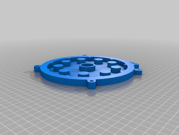
After researching quite a while and never finding a complete working printable 3 phase Permanent Magnet Alternator I decided to design one. In all honestly I dropped out of Engineering my first year so everything is close but will need a little TLC to get it right. After many posted updates the project is nearing completion. Please check back weekly for the latest printable files. Requires print area of 8.3 inch x 7.25 inch x 2 inch. Last updated Files 2/1/2015. Updated notes 2/23/2015 Instructions This is a PMA with 9 coils wired for 3 phases. ~108 windings per coil (not sure what gauge wire I can get away with yet, trying for 20 volts in 2 m/s wind speeds I'll pair it with a MPPT charge controller so that I can convert the excess voltage to amperage. I'm using 12 magnets per plate (2 plates) that are round 3/4 inch wide by 1/8 inch thick N52 Strength Neodymium (I've provided an option for 1/4 inch thick magnets). The whole thing is in inches because the magnets were in inches otherwise I would have used mm so please excuse that if you can. I'm expecting to use 1/2 threaded rod for the axil and I'm using 1 1/8 OD x 1/2 ID x 3/8 thickness bearings (they get pressed into the casing once you have taken a xacto to the edges of the hole. Just don't take off too much, It needs to be a tight fit. Completed Parts Winder 1+2 Casing with mounting plate Casing without mounting plate Magnet plates (two options 1/8 or 1/4 inch thick magnets options) PMA coil plate Parts that are designed and printed and tweaked more than once Parts that have never been printed spacers that go up against the bearings. Spacers should be nylon washers if you don't have nylon to print with. You will need to buy: 1/2 inch threaded rod for the axle. x24 - Magnets 3/4"x 1/8" round N52 magnets Wire 18 gauge 300 feet. Bearings 1 1.8 OD and 1/2 ID. epoxy Resin (I'm using TAPS plastic general purpose). Buy Triple what you think you will need because you will have print a couple of coil plates and practice a couple of times. You will only get one shot at it. x4 - 1/4 inch diameter bolts and washers and nuts to hold casing together. x4 - 3/8 mounting bolts to attach casing to mounting bracket. x2 - O Rings - 6 1/2 ID x 7 OD (available on Amazon) alternatively use silicone glue leaving 1/16 exposed like an O-Ring. So I did the math to make sure that I had the windings right to get the voltage but I won't know the amperage until I build it. The Epoxy resin is poured over the coil plate after you have wired it completely (plate will survive the temperature of the Epoxy Resin but make sure you cure in slowly). When cured It's then one combined part of Thermal plastic and hardened resin to never be separated. Steps: Order parts Print parts 1 and 2 of the winder Print two magnet plates. Print one coil plate Print two casings (one of each or both of the same one it's up to you) Wrap coils to the edges of the winder trying for 108 windings. Place the coils in the coil place over the holders. Read up on how to solder every third coil together because you aren't going to get that here. The coil plate is designed to pour resin into. First make a small batch of Resin and paint the outside of it so that the resin doesn't seep out be conservative on application but apply all over. Once that cures you are ready do assemble and pour. You poor it up to the edge and no farther. Cover it and put books on it while it hardens. After it hardens, clean it up. Cut off the stuff that will interfere with the magnet plate (sand in smooth on the bottom) or with the housing fit. The magnets get put into the place alternating N S N S. After cleaning out the burs and irregularities in the casing bearing area, press the bearings into place. Will likely take blocks of wood and a vise. The parts are assembled with the O rings on either side of the coil plate. Press the O Rings into the housing with your thumb. Use long 1/4 inch threaded bolts to hold the thing together through the holes in the casings. The winder can be printed out of PLA or anything stiff but it's going to be twisted by a drill so it needs a certain amount of strength. The rest needs to be both Stiff, strong and not warp while printing and stand up to outdoors and direct sunlight (I'm going to go with colorless PLA due to it's low shrink low warp). I've heard that Colorfabb XT is a viable alternative. If heat turns out to be a problem for the coil plate will switch to XT for that part. Using PLA... Casing can be printed infill at 30% but make sure it's set to 4 layers walls. Magnet plate can be printed infill at 20% - PLA is surprisingly rigid. Coil plate needs to be printed at 30% infill to resist warping with the resin. Rectifier info: http://www.reuk.co.uk/OtherImages/3-phase-full-wave-bridge-rectifier-circuit.jpg Wiring info: History: 2/23/2015 printer has been down for about a week so I haven't been able to print the stator (coil plate). However I practiced with the resin on old prints of it and found some interesting things. The coil plate is porous so in order to not have the resin seep out when trying to fill it make a small amount of resin and paint the outside of it. When that cures it will be seep proof. 2/1/2015 After printing everything I increased the recess on the O Ring (on both casings) so only 1/16 of it should be exposed. I added a wire grove in the winder so it will hold the wire tight when winding. After printing the coil plate and filling it with Resin I increased the depth so that there was a little margin to play with because the coils will undoubted expand. I also added wire grooves to the wire nut and reduced the wire nut points from 4 to 3 since you don't need a ground. On the magnet plate I recessed the nut another 1/16th of an inch. Lastly for those who would prefer to use 1/4 inch thick magnets I created a second magnet plate to accommodate those folks. At this point I wish I had used 1/4 inch magnets instead of 1/8. It would essentially double the field strength. That is it for updates until I get all of the pieces assembled. I'll most likely add printable spacers so that you can limit the movement on the rod, they go up against the bearing (1/2 inch inner diameter cylinder of the length necessary for the spacing). 1/30/2015 I've modified the wall diameter to to allow for recessing the O-ring so only 1/16 is exposed to compress (walls increased thickness from 1/4 to 1/2 inch). Overall size increased by 1/4 inch. I found that the magnet plate size when printed in PLA was perfect fit for the magnets and they pressed in with my thumb (with effort) and didn't come out even when trying to use the rest of the magnets to pull them out so I feel confident in not using epoxy on the magnet plates. I tightened the tolerances on the bearing recess it should be a tight fit now. I modified the coil plate match the casing wall thicknesses and dimensions. This should be the last design round. 1/24/2015 I've modified the dimension of the casing to give it a thicker mounting plate with bigger holes for 3/8 inch bolts. I also modified the dimensions to give only 1/16th of an inch between the magnets and the coil plate. I've also taken the case STL and created a no mounting plate version of the case. You can use either case STL or both, it's up to you, just don't forget the two rubber O-rings. I also modified the coil plate to have terminal bolt holes to attach the 4 wires to (3 phases and 1 ground). 1/23/2015 I've redesigned several parts after attempting prints. The design is now intended to print using PLA with a 100% fill. The magnets get epoxied into place. The coil plate after wiring and placing the coils will get a pour of epoxy resin into the plate up to the top to hold the whole thing in place. It will add rigidity to it and act as a thermal mass to reduce heat into the PLA surrounding it. I'm going to attempt low fill pieces tomorrow to check fit to include fit of the rubber O-rings. Also realized that you will need to create 4 bolts to tie the wires to that will need holes and you will need drainage holes that will need to be drilled based on orientation.
With this file you will be able to print PMA Permanent Magnet Alternator with your 3D printer. Click on the button and save the file on your computer to work, edit or customize your design. You can also find more 3D designs for printers on PMA Permanent Magnet Alternator.