Polypanels Shaft System
myminifactory
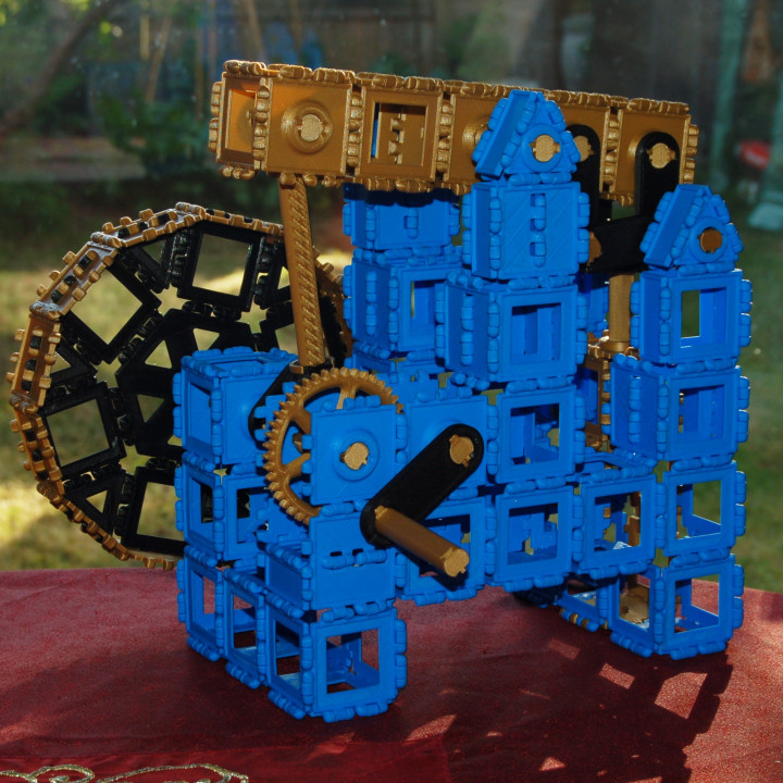
To see the model moving click here and here. UPDATE: I have re-uploaded all the parts (except the shafts) as some of the dimensions were very slightly off; I was in a bit of a rush to design the system initially. I have included the 'shaft bearing core' part in STL, STEP and Fusion 360 file formats so that you can make your own parts to fit the shaft system. I have also included the Fusion 360 file for the entire shaft system (yeah I should have made separate files for each part but again I was in a rush :P) so you can tweak and adapt it to your hearts content. The idea of this system is to add mechanical moving parts and features to the polypanel ecosystem while keeping them easy to print and use. There is a lot more I want to add to the system, and will release at a later date e.g. bevel gears (for 90 degree turns etc), cams and followers, worm gears, helical gears, wheels, pulleys, 608 bearing support adapters etc. I will add new components in groups as new uploads. No support material is needed for the parts. As you can see from the pictures, I have made a working model of a beam engine using this shaft system. It includes a Watt's Parallel Motion Linkage (the black linkage on the right) which translates the beams rocking motion into very straight linear motion for the piston rod. No extra hardware was used in the model, just the printed part files here as well as some of the standard polypanels by Devin Montes and my square 'centre connector' panel to add reinforcement and thinner shapes in places. The system is based around a 12mm nominal diameter shaft with 5mm 'unit spacing' along the shaft. I chose this because each square polypanel is 45mm wide between the connectors, so this allows the shaft components to fit neatly into the polypanel system. The core bearing is 5mm thick, this leaves 40mm or 8 component 'units' across one polypanel width. The shafts have a flat along one side for a couple of reasons. Firstly it allows them to be more easily printed, flat on the bed without support. Secondly it gives a place for the components to 'key' to the shaft and turn with them. Almost all components are free to turn and slide on the shafts at first. All the bearings have a key hole shaped into them which fits a small piece 'shaft key'. Once added to the bearing, it matches the shape of the flat on the shaft and will then couple the component to turn with the shaft, but still allows it to slide along the shaft freely. This allows you to create simple linear sliding components or more advanced mechanisms like gears which can slide and engage/disengage other gears along a shaft; could be used to make a simple gearbox for example. In order to lock the components along the shafts, you use the very small 'pin' part which fits into a small angled slot in the bearing. The pin also locks into the diagonal slots on the shafts (which make them look like baguettes) fixing the component in place. It is quite fiddley to install and remove on many parts, but holds components in tight spots or at the end of shafts. (I find it easiest to remove by pushing with a piece of 1.75mm filament where possible). The easier way to lock the component along the shaft is to add a 'Shaft spacer clip' either side of it. These simply clip onto the shaft at any point and lock into the lines, also acting as a 5mm spacer. They aren't particularly strong though and will slip if pushed too hard so I made the 'spacer lock' which fits around it and makes it much more secure. The parts generally have 0.3mm tolerances between them, since most of the components were printed at 0.3mm layer heights for speed. Some of the parts may be loose if lower layer heights are used so you may need to counteract this with settings in your slicer e.g. contour xy compensation in ideamaker for example. Other components: Polypanel triangle shaft bearing. The basic triangle from Devin Montes with a bearing support through the centre. Polypanel hexagonal shaft bearing. The hexagonal polypanel with a bearing in the centre. Shafts of various lengths (which I used for the model). Small gear. A 15 tooth gear with a pitch diameter of 22.5mm, three of them will fit between two parallel shafts in adjoining square polypanels. All the gears are involute gears with a module of 1.5mm and pressure angle of 20 degrees (made with the involute gear generator script in Fusion 360). The gears also have about 0.1mm contour shrinkage (0.2 backlash setting) to account for printing tolerances. Printed at 0.3mm layer height they work smoothly with no backlash for me. Large gear. A 45 tooth gear with a pitch diameter of 67.5mm. Meshes with a small gear between two parallel shafts, giving a ratio of 3:1 (as shown on the model) Link 2-hole. A link with two holes, spaced between two parallel shafts in adjoining square polypanels. Link half 2-hole. A shorter link with two holes, spaced halfway between two parallel shafts in adjoining square polypanels; allows two small gears to mesh together. Link 3-hole. The same as 'Link 2-hole' but with an extra hole in the centre. This allows three small gears to mesh together in a line, and connect two shafts in adjacent square polypanels. Shaft 'T' joint. A 'T' joint where shafts can pass straight through the top of the 'T', and attach directly to the base of the 'T'. Used to make links of various lengths. Shaft end clip. Attaches the end of shafts into the base of the T-joint. More components will be released in later uploads.
With this file you will be able to print Polypanels Shaft System with your 3D printer. Click on the button and save the file on your computer to work, edit or customize your design. You can also find more 3D designs for printers on Polypanels Shaft System.