Power Bank for Onewheel or Electric Skateboard (with Power Tool Battery)
prusaprinters
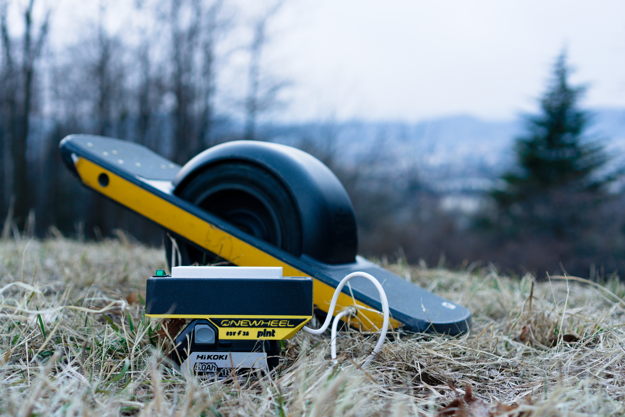
<p>There have been times when I wanted to ride further or longer with my Onewheel Pint, but had to turn around, because otherwise I might run out of power in the middle of the forest. Luckily, there are technical solutions that can tackle my range anxiety. One of them is a power bank. Adding some juice to my board in the middle of nowhere sounded awesome. Inspired by <a href="https://www.mariocontino.com/articles/diy-power-bank">Mario Contino and his DIY Power Bank</a>, I wanted to build my own. But instead of buying battery cells and building my own battery pack, I decided to use a power tool battery - which is pretty much what you can order from <a href="https://carvepower.com/">CarvePower</a>. I though, wanted to use the power tool battery that I already had at home - a Hikoki 18V 5Ah battery. Neglecting the losses in the energy transfer, this battery could add 90Wh to my board, which is about 60% of my original Onewheel Pint battery, or rather about 6km of additional range.</p><p>I designed a 3D printable converter enclosure with two main parts - the <i>Top Enclosure</i> and the <i>Slide Enclosure</i>. The Top Enclosure holds the boost converter, power switch and battery charge indicator and is rather independent from the used battery. The Slide Enclosure is the part specific to the used battery. So, you could use my Top Enclosure and creat your own Slide Enclosure. However, I have also created a part called <i>Bottom Enclosure Line</i>, that, combined with the <i>Top Enclosure Line</i>, allows the converter to be used in a “line installation” (input and output cables).</p><p>You could fit either variant's parts all at once on a Prusa MINI printbed. I printed the main parts (top and slide enclosure) with PETG. Just the slide enclosure needs a little bit of support structure - everything else can be printed without supports.</p><figure class="image image-style-align-left image_resized" style="width:45.92%;"><img src="https://media.prusaprinters.org/media/prints/143727/rich_content/d485e10a-41c5-4026-965e-0206cb4d95e6/hi18_ow-pint-1_crop.png#%7B%22uuid%22%3A%22dfaf203c-d4f9-4d6b-aed9-5d572584cc6d%22%2C%22w%22%3A1614%2C%22h%22%3A1024%7D"></figure><p>In the following paragraphs, I will list the parts you need for your build and describe the special features of my design. However, the assembly should be straightforward. I will also add some information about the electronics, but I cannot guarantee their correctness. <strong>Everything you do is at your own risk. Improper workmanship, regarding the electronics, can lead to injuries and damages.</strong></p><p> </p><h3><strong>Standard Parts and Electronics</strong></h3><p>Both variants (<i>Enclosure for Hikoki 18V</i> and <i>Enclosure for Line Installation</i>) need the following parts:</p><ul><li>Rocker Switch (IRS-101)</li><li>1200W DC Boost Converter (about 20€ on <a href="https://www.amazon.de/gp/product/B07VQ89HX4/ref=ppx_yo_dt_b_asin_title_o02_s00?ie=UTF8&psc=1">Amazon</a>)</li><li>Battery Charge Indicator (MH-DL18S) (about 3€)</li><li>In-line Fuse Holder + Fuse (for the output side)</li><li>Some Cables</li><li>Connector Plug for your board (Onewheel Pint, e.g., GX12-2pin Aviation Plug)</li><li>Threaded Inserts M3 (10 pcs.)</li><li>Socket Head Screw M3x8 (10 pcs.)</li></ul><figure class="image image-style-align-center image_resized" style="width:75%;"><img src="https://media.prusaprinters.org/media/prints/143727/rich_content/87e04044-4c2b-48d2-b729-23c0e6da5af6/exp_hi18_ow-pint_square.png#%7B%22uuid%22%3A%229ecea87b-0348-4960-85c8-8e31e5bdeabe%22%2C%22w%22%3A1106%2C%22h%22%3A1106%7D"></figure><h4>Wiring</h4><p>For the Hikoki 18V power bank, you also need two 6.35mm crimp terminals (for the power connection between the battery and the converter). Here is how I wired my parts:</p><figure class="image image_resized" style="width:75%;"><img src="https://media.prusaprinters.org/media/prints/143727/rich_content/b0c72275-7252-4dfe-87ca-2356c3b53da1/dsc05857.jpg#%7B%22uuid%22%3A%2208cfedda-c40c-4b2d-b455-313c3e813a1f%22%2C%22w%22%3A1920%2C%22h%22%3A1084%7D"></figure><p>(The enclosures seen in the picture are not of the latest version.)</p><h4>Hikoki 18V Battery</h4><p>I opened up my Hikoki 18V 5Ah battery to see which lithium ion cells are used, so I could look up the discharge limits of my battery. The incorporated cells were LG 18650HE2 2500mAh battery cells. According to the <a href="https://www.powerstream.com/p/LG-ICR18650HE2-REV0.pdf">product specification from LG</a>, the cell's limits are as follows:</p><figure class="table"><table><tbody><tr><td>Max. Discharge Current (for continuous discharge)</td><td>20A</td></tr><tr><td>End Voltage (Cut off) for constant fast discharge current (10A, 20A)</td><td>2.5V</td></tr><tr><td>End Voltage (Cut off) for constant standard discharge current (0.5A)</td><td>2.5V</td></tr><tr><td>Operating Temperature (discharge)</td><td>-20 ~ 75°C</td></tr></tbody></table></figure><h4>Boost Converter Setup</h4><p>Here is an overview on where to connect and adjust the boost converter (sorry for it being in German, but I reckon, it is better than nothing):</p><figure class="image image_resized" style="width:80%;"><img src="https://media.prusaprinters.org/media/prints/143727/rich_content/2e2d1800-82d0-4cb7-9dd3-d60a9d9d557f/step-up-konverter-dc-dc-wandler-dc-1200w-20a-anschluesse-pinbelegung.jpg#%7B%22uuid%22%3A%22eb89c8ca-1649-4e4d-a44d-82839b9dd523%22%2C%22w%22%3A1913%2C%22h%22%3A1180%7D"></figure><p>Since I built the power bank for my Onewheel Pint, I have set the output voltage to 63V. With the information about the cells in my battery, I have set the minimum voltage on the converter to approximately 15V. Finally, I have set the current limiter on the converter to 3A (which leads to a current draw of roughly 10A at my 18V battery). These values lead to the same charge rate as the original Onewheel Pint Ultracharger.</p><p><strong>Please inspect the information about your board, charger and power bank batteries before you set up your boost converter!</strong></p><p>You could attach a 12V 40x40mm fan onto the heat sink of the boost converter, but you might not need one. Thus, I designed a plug to cover the 12V output connector.</p><figure class="image image_resized" style="width:50%;"><img src="https://media.prusaprinters.org/media/prints/143727/rich_content/00e2f6d6-abd3-4dd6-846c-0460b2e7c83b/12v-plug-3_crop.png#%7B%22uuid%22%3A%22c53db512-9330-4421-9cc5-d210441542f3%22%2C%22w%22%3A2373%2C%22h%22%3A1235%7D"></figure><p> </p><h3><strong>Enclosure for Hikoki 18V</strong></h3><p>If you want to attach your converter on top of your Hikoki 18V battery, these prints are for you:</p><ul><li>Top Enclosure</li><li>Slide Enclosure Hi18</li><li>Cable Grommet FLEX/PETG</li><li>Optional: Inscription Left/Right </li><li>Optional: 12V Plug</li></ul><figure class="image image-style-align-center image_resized" style="width:89.78%;"><img src="https://media.prusaprinters.org/media/prints/143727/rich_content/2f1bba0a-b109-4e31-b178-ba9dd4e41088/hi18_ow-pint-2_crop.png#%7B%22uuid%22%3A%22fb03c469-9247-4953-85e8-5baa5426ed54%22%2C%22w%22%3A1643%2C%22h%22%3A1108%7D"></figure><h4>Top Enclosure</h4><p>I hope that the hole spacing on the boost converters do not deviate too much between the manufacturers. However, when you join the threaded inserts with the top enclosure, you will notice that you have some freedom in the alignment of your threads.</p><p>The 8mm long screws are a bit too long for the attachment of the boost converter. I recommend using two washers per screw (or just shorter screws), so you don’t pierce into the top of the enclosure.</p><p>The rocker switch can be attached by just pushing it into the enclosure from the outside. If you use a switch with different dimensions, you can simply edit the stl file in the Prusa Slicer.</p><p>The battery charge indicator is attached from the inside. It has a snug fit between the enclosure and the indicator's LED housing. Additional snap-fits hold the indicator in place.</p><p>I also incorporated some snap-fits to nicely route the cables of the battery indicator to the input terminal.</p><figure class="image image_resized" style="width:75%;"><img src="https://media.prusaprinters.org/media/prints/143727/rich_content/995cc518-3ec5-4e84-8e57-537a2f840239/top_enc-3.png#%7B%22uuid%22%3A%2258a4b3e2-db24-4217-abc0-9149b593141b%22%2C%22w%22%3A1698%2C%22h%22%3A1039%7D"></figure><h4>Slide Enclosure</h4><p>The crimp terminals can be pressed into the slots of the slide enclosure. The drill that I use also has a connection with the “LD” slot of the battery. I assume it is used for deactivating the drill, so the battery is not drained below its limits. However, I currently just set the cut off voltage on the boost converter. If you do it likewise, just don’t forget to switch off the power bank (and remove the battery for safety), so the LEDs don’t drain the battery below the end voltage of the cells.</p><p>There are two variants of the cable grommet. If you have a flexible filament at home, you can print the <i>Cable Grommet FLEX</i> file. Alternatively, you can print the <i>Cable Grommet PETG</i> file. Both variants are simply pressed into the slide enclosure. The cable grommets are designed for a cable with a diameter of 5.5 or max. 6mm.</p><p>The slide enclosure also incorporates a strain relief on the output cable (which should have a diameter of approx. 5.5mm). The cable will be pinched when the slide enclosure is attached to the top enclosure. </p><figure class="image image-style-align-center image_resized" style="width:75%;"><img src="https://media.prusaprinters.org/media/prints/143727/rich_content/ff4c62ac-5a2d-4641-b8d1-a03229ea13a5/slide_enc-2_crop2.png#%7B%22uuid%22%3A%229e4d9bdb-1e80-4e55-8026-15641bc123a4%22%2C%22w%22%3A1840%2C%22h%22%3A1376%7D"></figure><h4>Inscription</h4><p>I also created inscriptions that can be added to the slide enclosure. You could use it to create a negative volume or fuzzy skin on the slide enclosure. Or you get fancy and print the inscription with a flexible filament onto the slide enclosure.</p><figure class="image image-style-align-center image_resized" style="width:75%;"><img src="https://media.prusaprinters.org/media/prints/143727/rich_content/cc4dfe5d-5562-4aa1-8964-6213329b27a2/dsc_0478.jpg#%7B%22uuid%22%3A%22a79ee67d-f7a5-4b65-bb0f-1cbab89169e8%22%2C%22w%22%3A3772%2C%22h%22%3A2509%7D"></figure><p>(I printed some brackets with magnets that hold the slide enclosure on the build plate.)</p><p> </p><h3><strong>Enclosure for Line Installation</strong></h3><p>If you would rather have the boost converter in line with your battery, instead of on top of your battery, these prints are for you:</p><ul><li>Top Enclosure Line</li><li>Bottom Enclosure Line</li><li>Optional: Cable Grommet FLEX/PETG</li><li>Optional: 12V Plug</li></ul><figure class="image image_resized" style="width:89.89%;"><img src="https://media.prusaprinters.org/media/prints/143727/rich_content/487b6bbd-2c4b-4bcb-9088-5eb8909bd4b5/line_enc-1_crop.png#%7B%22uuid%22%3A%22533ee937-f1cf-462a-9131-84feb65f25bb%22%2C%22w%22%3A1350%2C%22h%22%3A759%7D"></figure><p>The Top Enclosure Line has additional vents on the sides and the nose for the cable strain relief is removed, since the Bottom Enclosure Line is just a flat cover. I did not create any through holes for the input and output cables. You can simply add them in the Prusa Slicer with whatever diameter you want, e.g., in the triangular corners of the top enclosure.</p><p> </p><h3><strong>Future Versions / Other Slide Enclosures</strong></h3><p>I would be happy to see some remixes with slide enclosures for different power tool batteries. I added a dxf file of the interface, so you don’t have to measure the stl files. Since I have access to a Hikoki 36V battery, I might upload a slide enclosure for it later on.</p><p> </p><p>Here is the video from Mario Contino that inspired me to create this project:</p><figure class="media"><oembed url="https://www.youtube.com/watch?v=PZHXNsdi4eI"></oembed></figure>
With this file you will be able to print Power Bank for Onewheel or Electric Skateboard (with Power Tool Battery) with your 3D printer. Click on the button and save the file on your computer to work, edit or customize your design. You can also find more 3D designs for printers on Power Bank for Onewheel or Electric Skateboard (with Power Tool Battery).