Precision Adjustable Z Endstop Holder and Constraint
thingiverse
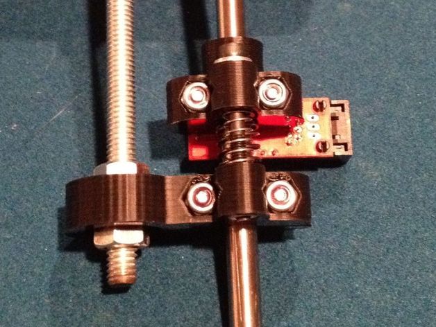
Create an adjustable Z-axis endstop holder with integrated screw constraint bearing for Prusa printers using the following steps: 1) Print, 2) trim support, 3) ream M8 hole, 4) install 608 bearing in cup, 5) attach optical endstop, 6) optionally use nut to secure top of bearing, 7) assemble parts on smooth rod, 8) loosely attach Clamp/Bearing mount, 9) assemble adjustment bolt, and 10) move clamp to final position. You will need M3 and M4 bolts, nuts, washers, springs, an optical endstop, and a 608 bearing. Note that the provided .stl file is sized for M3 bolts. The springs can be sourced from Home Depot's Everbilt #471864 spring assortment kit.
With this file you will be able to print Precision Adjustable Z Endstop Holder and Constraint with your 3D printer. Click on the button and save the file on your computer to work, edit or customize your design. You can also find more 3D designs for printers on Precision Adjustable Z Endstop Holder and Constraint.